Continue to Site

Welcome to our site!

Electro Tech is an online community (with over 170,000 members) who enjoy talking about and building electronic circuits, projects and gadgets. To participate you need to register. Registration is free. Click here to register now.

  • Welcome to our site! Electro Tech is an online community (with over 170,000 members) who enjoy talking about and building electronic circuits, projects and gadgets. To participate you need to register. Registration is free. Click here to register now.

Help with an electronic geocache project

Status
Not open for further replies.

mallaht

New Member
Hi, all, new here and to electronics. I'm looking for help and advice..

I am trying to build a gadget cache for a hobby called Geocaching. This is a hobby where you hide a "cache" (usually a watertight plastic container or an ammo can) in the woods somewhere, post the coordinates online and other people go searching for it using a handheld GPS. The cache usually contains trinkets for trading and a logbook for recording the find. Search on geocaching if you're interested.

The cache will be based on a popular murder mystery board game, where you have to collect evidence to ascertain the correct murderer, weapon, and room. Once you have the information you push the corresponding buttons on the front of the cache and that will activate an electromagnetic lock which reveals a compartment where the logbook will be hidden.

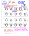
The switch type I selected to use is a NO/NC 5V microswitch. The majority of them are cabled up as NC apart from the correct answers which are cabled as NO. The lock is a 6V 1.5A electromagnet Solenoid Lock. The cable I am using is 22awg stranded wire. I have cabled very similar as the below diagram

1631538100278.png


When I push the NO switches, to complete the circuit, the lock does not open. I'm only getting 3.77V which is not enough to fire/open the lock. Is this due to voltage drop due to the type of wire that I've used or an incompatibility between the components that I've selected to use?
IMG_1503.jpeg

Any help or advice will be gratefully received.
 
Most likely the AA cells you are using cannot give enough current. You need cells intended for high current loads; ones that are recommended for such as digital cameras should work. Adding a large capacitor across the battery pack will also help, as that can supply some of the current for a short time to get the solenoid moving.

Note that batteries / cells drop in voltage with use, and a four cell pack will be down to around 4V by the time the batteries are near empty.

Using very thin wire could also add to the problem, but if the total is only a couple of foot then just about anything of a reasonable gauge should work, down to 7/.02 as a reasonable minimum.

The type you are using is larger than that and should be fine, unless it's very long - some yards or metres in total, rather than 2 - 3 ft total.
 
I suspect it's probably a combination of everything - low current switches, thin wire, and low capacity batteries.

Easy to test - stick your black meter lead on the -ve connection of the solenoid (right on it's terminal) then trigger the lock with the switches (you may need a friend for this) and test voltages through the circuit.

First test the voltage on the -ve side of the battery pack - this 'should' be zero, but anything other than that is the voltage drop across the wire from solenoid to battery pack - write it down.

Then put the probe directly on the positive side of the battery pack, this should be 6V or so - and is testing the battery pack (and the -ve lead again) - write that down.

Then go along each switch in turn, measure the voltage in and out of each switch - write them all down :D

With all that information it's now just simple maths to work our where the voltage is getting lost, and if it's a single cause, or a little bit everywhere.
Thank you for the troubleshooting steps

I can not test the connection from the negative side of the solenoid to the negative side of the battery pack as the lock is a sealed unit with wires. I've attached the negative side directly to the battery pack.

I completed the other tests as you described.

I am getting 5.99v from the battery pack.

I then connected the black meter lead to the negative wire of the solenoid and connected it to every terminal of each switch and only triggering the switches as I came to them. Everything was looking ok until I got to the 17th switch, the third NO switch. As soon as it was triggered, the meter dropped to 4.46v regardless of where I tested along the circuit, which would not trigger the lock.

I then re-cabled the third NO switch to an NC switch. When I triggered the two remaining NO switches the solenoid triggered.
 
This type of microswitch usually has decent current-handling capability (as opposed to tactile switches) although these are unmarked and make no claims about it.

Swap out the switch and you should be in business.
 
Thank you very much for the warm welcome and the advice that got this working.

I have another cache idea that I can't get working using reed switches so I'm sure I'll be posting another post soon.
 
Your solenoid has a DC resistance could be too low, on the other hand , all it takes is one bad cell to drop 1.5V
 
After getting the puzzle to work a couple of times last night It seems that the issue has not been fixed. It exhibits similar behaviour as last time. If I connect the battery pack to the solenoid it fires. If I connect the circuit as designed, the solenoid will not fire, I changed each one of the NO switches over to NC one at a time and each time when I pushed the last button, the voltage dropped to 4.5V.

In my head, the next steps would either be
  • Swap out the wire for a thicker gauge? like this
  • Swap out the microswitch for a different type/rating? like this?
Would that be correct?
Before you fix anything , you normally prove the cause of the problem, bad battery ESR or wrong solenoid choice with low ESR for capacity of equally aging batteries. Test/Measure/diagnose/show all component specs. then the answer is simple.
 
After getting the puzzle to work a couple of times last night It seems that the issue has not been fixed. It exhibits similar behaviour as last time. If I connect the battery pack to the solenoid it fires. If I connect the circuit as designed, the solenoid will not fire, I changed each one of the NO switches over to NC one at a time and each time when I pushed the last button, the voltage dropped to 4.5V.

In my head, the next steps would either be
  • Swap out the wire for a thicker gauge? like this
  • Swap out the microswitch for a different type/rating? like this?
Would that be correct?
As I explained previously - simply measure the voltages EVERYWHERE and work out where you're losing it, it's no good guessing. But the entire premise seems pretty flawed, small batteries, thin wires, low power switches, and a high current load.
 
Here are my results, as you said it seems flawed. Am I able to achieve a working design without changing the battery or solenoid choice?

1631692966260.png
 
As you can see from the figures, you're making a slight loss in every switch, and also in every piece of wire.

A simple solution would to add a transistor to drive the solenoid, a diode across the solenoid, and a couple of resistors - use short thick wires from battery to transistor to solenoid, and you could still use thin longer wires to the switches. Here's what I'm talking about, you can play with the resistor values (but these should work OK - you want plenty of base drive), for the transistor a small power transistor like a TIP41, and a 1N4001 for the diode.

As I said you want short thick wires between battery, solenoid, and transistor to avoid voltage drop.

Solenoid_Sw.GIF
 
Last edited:
- assuming 4 Ohms I calc'd is correct from website R=V/I here is my quick analysis of where you losses are:
- Pls verify coil ohms , buy FET and move tiny board near solenoid. Make that current loop as SMALL AS POSSIBLE

Battery 25% => Get a bigger pack or LiFe cells
switch and wires 28% => Use Nigel's schematic . Note R2 is 25 x coil R ... Good ratio to use for a big NPN Power Transistor. But you may want a logic level MOSFET.
Your results 53% loss from poor design .
Your goal ought to be < 1% losses in battery, switch and wires. but settle for 5% for cost or heat compromise if absolutely necessary.
Heat = high failure rate

Since power loss is proportional to R. the above means all R's must be < 1% of 4 Ohm load or 40 mOhm max total. so allow 10 mOhm for wire based on AWG and mOhms /m and keep short, move electronics to solenoid. then 30 mOhms max for transistor FET @ Vgs = 4.5V

1631720368594.png


In future define your 0V point as VBat- not Vbat+ = BLK wire in Common (-) of DMM.

Lithium Cells work best , long life or Li-Ion ,slightly higher voltage. (10%V 20% P)
1631717408016.png


The tab is also Drain (+) for Nch FET.

$0.57 FET Through hole , works well at 4.5V 9 mohm https://www.digikey.ca/en/products/detail/onsemi/NTD4979N-35G/13439150 in stock
Any 100mA ~ 1 A diode will do for flyback pulse ~ 1.5A 1ms

Bottom Line is Battery needs to be 5x bigger or better minimum preferably 25x better. and you need a transistor switch in a small current loop with battery , coil and transistor.
 

Attachments

  • 1631716848231.png
    1631716848231.png
    84.4 KB · Views: 194
Last edited:
As you can see from the figures, you're making a slight loss in every switch, and also in every piece of wire.

A simple solution would to add a transistor to drive the solenoid, a diode across the solenoid, and a couple of resistors - use short thick wires from battery to transistor to solenoid, and you could still use thin longer wires to the switches. Here's what I'm talking about, you can play with the resistor values (but these should work OK - you want plenty of base drive), for the transistor a small power transistor like a TIP41, and a 1N4001 for the diode.

As I said you want short thick wires between battery, solenoid, and transistor to avoid voltage drop.

View attachment 133708
Thanks for your reply. I've ordered the suggested components. Would a .75mm or 1mm cable size be better suited between the battery, solenoid, and transistor?
 
- assuming 4 Ohms I calc'd is correct from website R=V/I here is my quick analysis of where you losses are:
- Pls verify coil ohms , buy FET and move tiny board near solenoid. Make that current loop as SMALL AS POSSIBLE

Battery 25% => Get a bigger pack or LiFe cells
switch and wires 28% => Use Nigel's schematic . Note R2 is 25 x coil R ... Good ratio to use for a big NPN Power Transistor. But you may want a logic level MOSFET.
Your results 53% loss from poor design .
Your goal ought to be < 1% losses in battery, switch and wires. but settle for 5% for cost or heat compromise if absolutely necessary.
Heat = high failure rate

Since power loss is proportional to R. the above means all R's must be < 1% of 4 Ohm load or 40 mOhm max total. so allow 10 mOhm for wire based on AWG and mOhms /m and keep short, move electronics to solenoid. then 30 mOhms max for transistor FET @ Vgs = 4.5V

View attachment 133724

In future define your 0V point as VBat- not Vbat+ = BLK wire in Common (-) of DMM.

Lithium Cells work best , long life or Li-Ion ,slightly higher voltage. (10%V 20% P)
View attachment 133719

The tab is also Drain (+) for Nch FET.

$0.57 FET Through hole , works well at 4.5V 9 mohm https://www.digikey.ca/en/products/detail/onsemi/NTD4979N-35G/13439150 in stock
Any 100mA ~ 1 A diode will do for flyback pulse ~ 1.5A 1ms

Bottom Line is Battery needs to be 5x bigger or better minimum preferably 25x better. and you need a transistor switch in a small current loop with battery , coil and transistor.
Thank you for the analysis, it will take me some time to read and understand the detail that you have provided but I understand the bottom line.
 
Just use Ohm's Law and Watt's Law, look them up
 
As you can see from the figures, you're making a slight loss in every switch, and also in every piece of wire.

A simple solution would to add a transistor to drive the solenoid, a diode across the solenoid, and a couple of resistors - use short thick wires from battery to transistor to solenoid, and you could still use thin longer wires to the switches. Here's what I'm talking about, you can play with the resistor values (but these should work OK - you want plenty of base drive), for the transistor a small power transistor like a TIP41, and a 1N4001 for the diode.

As I said you want short thick wires between battery, solenoid, and transistor to avoid voltage drop.

View attachment 133708The
The TIP41 is about 1/4 Ohm at 1.5A with 150 mA input from 6V which if same batteries is 1 ohm x 4 = 6 Ohms after some aging , means with R2 only provides about 50mA for Ic/Ib= 60 and voltage rises (loss) Vce(sat)= 1V or more. Into the linear region limited to by hFE tolerances. Typically at Vce(sat) Ic/Ib is about = 10% of hFE nominal in the datasheet , but that has a wide tolerance. So it might work for a while or not with better batteries, so R1= 5V/150mA= 33 Ohms would extend use of batteries since it is only used for a short duration but reduce T1 switch losses . So a FET is more desireable and cheap here.
 
Hey, when it will be ready can you share it with us? I am very curious to see what came out. By the way, will you also promote it? I think it will have a great success.
 
Hey, when it will be ready can you share it with us? I am very curious to see what came out. By the way, will you also promote it? I think it will have a great success.

Hi, Its was completed a few weeks ago and published on 3rd October. If you are a cacher is GC is GC9EJFY.

After implementing the design from Nigel Goodwin's message on 15th Sept, it worked flawlessly. I've made a short video of it working and uploaded it to youtube.
 
Status
Not open for further replies.

Latest threads

New Articles From Microcontroller Tips

Back
Top