Hi,
I'm totally new to analogue electronics, and am trying to teach myself about transistors.
I need to drive 20 LEDs, connected in parallel, from the output of an IC, that can source 150mA.
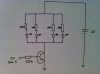
Would the attached circuit be correct or am I wrong? I've drawn 4 LEDs - there are actually 20.
The transistor data sheet show a min h(FE) of 50 (max is 250).
I calculate that the 625Ω resistor from the 5V output of the IC will provide a base current of 8mA (to a first approximation - I've ignored the 0.7V drop on the base-emitter diode).
With a gain of 50 (worst case), this means that the collector current will be around 400mA, which is needed to drive each of the LEDs in parallel, with around 20mA through each.
Is this correct or are my calculations wrong?
Now a few beginner's questions:
1) If I increased the base current, then I guess the collector current will also increase. But there will still only be 20mA through each LED because of the resistors, and therefore only 400mA will be drawn. What happens to the extra current?
2) Do I actually need the 150Ω resistors? The 400mA from the collector will be shared equally between the LEDs, meaning that only 20mA will pass through each, which does not exceed the maximum of 30mA. I guess I would have to measure h(FE) exactly for my particular transistor and use a computer simulation to take into account higher order effects?
Many thanks, and apologies if my questions seem silly,
Froskoy.
I'm totally new to analogue electronics, and am trying to teach myself about transistors.
I need to drive 20 LEDs, connected in parallel, from the output of an IC, that can source 150mA.
Would the attached circuit be correct or am I wrong? I've drawn 4 LEDs - there are actually 20.
The transistor data sheet show a min h(FE) of 50 (max is 250).
I calculate that the 625Ω resistor from the 5V output of the IC will provide a base current of 8mA (to a first approximation - I've ignored the 0.7V drop on the base-emitter diode).
With a gain of 50 (worst case), this means that the collector current will be around 400mA, which is needed to drive each of the LEDs in parallel, with around 20mA through each.
Is this correct or are my calculations wrong?
Now a few beginner's questions:
1) If I increased the base current, then I guess the collector current will also increase. But there will still only be 20mA through each LED because of the resistors, and therefore only 400mA will be drawn. What happens to the extra current?
2) Do I actually need the 150Ω resistors? The 400mA from the collector will be shared equally between the LEDs, meaning that only 20mA will pass through each, which does not exceed the maximum of 30mA. I guess I would have to measure h(FE) exactly for my particular transistor and use a computer simulation to take into account higher order effects?
Many thanks, and apologies if my questions seem silly,
Froskoy.