DG&H_MRRinN
New Member
Hello, I am new to the site.
I have been puttering around with various little projects that creating things.
But Im in a little pickle of confusion atm.
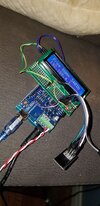
I am building a project where I am using an Arduino Mega, a L298 R3 motor shield. an ESP-01S Wireless WiFi Development board, and a LCD 16x2 screen.
So, I wanted to tidy things up, and make it a bit neater for myself, and I grabbed a PCB board to try and mount the WiFi and LCD too.
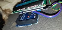
I put a header for the WiFi board to seat into, and pins for the board to seat into the Motor shield. connected up the 3.3V to the appropriate pins on the headers, Grounds to common Ground, and 5V to the LCD board. I then have 2 jumper wires going from the LCD board to pins 20/21. And 2 jumper wires going from the header to pins 18/19 for the WiFi board.
The LCD, no issues. The problem I am having is, when I plug the WiFi board into the headers, the WiFi board doesn't work. But, through hours of testing, I have found that when I connect 10cm jumper wires to the WiFi board, and the header I installed, (1 wire for each of the 5 pins in use), the WiFi board works like a charm! Any ideas on things to look for that might be causing this issue? Thanks in advance for checking out my problem, and offering advice on how to fix.


I have been puttering around with various little projects that creating things.
But Im in a little pickle of confusion atm.
I am building a project where I am using an Arduino Mega, a L298 R3 motor shield. an ESP-01S Wireless WiFi Development board, and a LCD 16x2 screen.
So, I wanted to tidy things up, and make it a bit neater for myself, and I grabbed a PCB board to try and mount the WiFi and LCD too.
I put a header for the WiFi board to seat into, and pins for the board to seat into the Motor shield. connected up the 3.3V to the appropriate pins on the headers, Grounds to common Ground, and 5V to the LCD board. I then have 2 jumper wires going from the LCD board to pins 20/21. And 2 jumper wires going from the header to pins 18/19 for the WiFi board.
The LCD, no issues. The problem I am having is, when I plug the WiFi board into the headers, the WiFi board doesn't work. But, through hours of testing, I have found that when I connect 10cm jumper wires to the WiFi board, and the header I installed, (1 wire for each of the 5 pins in use), the WiFi board works like a charm! Any ideas on things to look for that might be causing this issue? Thanks in advance for checking out my problem, and offering advice on how to fix.