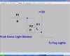
My cars interior lights dim on and off when you lock or unlock the doors.
I have a relay tapped into the interior lights to control a fog light.
When the interior lights dim to go off the voltage drops thus the relay chatters.
How can I make the relay stop chattering?
should I add a cap? where?
Thanks for your help!
-Anson
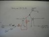
I have a relay tapped into the interior lights to control a fog light.
When the interior lights dim to go off the voltage drops thus the relay chatters.
How can I make the relay stop chattering?
should I add a cap? where?
Thanks for your help!
-Anson