Continue to Site

Welcome to our site!

Electro Tech is an online community (with over 170,000 members) who enjoy talking about and building electronic circuits, projects and gadgets. To participate you need to register. Registration is free. Click here to register now.

  • Welcome to our site! Electro Tech is an online community (with over 170,000 members) who enjoy talking about and building electronic circuits, projects and gadgets. To participate you need to register. Registration is free. Click here to register now.

Help with 433Mhz Transmitter + Receiver Module

Status
Not open for further replies.

Dan Alderaan

New Member
Hi all, i'm new to Electronic and want to make a transmitter + receiver for a project. Purched them off ebay **broken link removed** and trying to set them up to work together. Any help would be great cause ive just copied from a few youtube clips and web pages to understand it and it still not working. Am i missing something or are my resisters wrong or my whole setup is wrong?? Thanks in advance
 

Attachments

  • Receiver.jpg
    Receiver.jpg
    35.8 KB · Views: 242
  • Transmitter.jpg
    Transmitter.jpg
    37.3 KB · Views: 274
Hmm, perhaps someone else on this forum will be more familiar with those chips, but I can't say I know much about them or used anything similar, so I can't comment too much on that.

A couple thoughts, though:
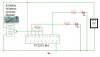
-On the transmitter circuit, that LED is connected directly across the 5V. Without a resistor to limit the current, it will probably burn out pretty much immediately if it is a standard LED.
-The eBay description of the receiver says that it requires a 50 Ohm, quarter wavelength antenna. Do you have that?

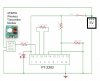
If you have an oscilloscope, you might try looking at the data input of the transmitter to determine if the chip is sending whatever data it is you are inputting. If no data is being sent by the chip, then the issue may be with the way you have the 2262 chip configured. If you are seeing data going into the input of the transmitter, then check the data output of the receiver. Is it receiving the data being sent? If not, there may be some issue with the RF transmitter or the RF receiver. Unless you have a very high frequency oscilloscope or other more specialized RF equipment, you probably won't be able to look at the radio signals directly, so you will probably have to consult whatever documentation came with those transmitter/receiver boards. The receiver appears to have a trimmer capacitor that may require adjustment for it to work properly. If there is data coming from the receiver board, then there could be some issue with your 2272 chip configuration.

Whatever YouTube videos or web pages you looked at might have more information if you are having issues using those 2262 and 2272 chips. If you would like to link them here, it may help us get up to speed on how you are using these chips and help debug whatever problem you are having.

Personally, this does not really strike me as an easy project for a beginner. Unless you copy everything the person in the video did perfectly on the first try, then debugging a circuit like this is not a trivial task. RF circuits are even more complex, especially in the hundreds of MHz like this, so we are basically going on blind faith that those modules you bought on eBay are working correctly.

Edit: I have attached the datasheets for those two chips for reference.
 

Attachments

  • PT2262.pdf
    371.1 KB · Views: 155
  • PT2272.pdf
    665 KB · Views: 162
Last edited:
I bought some Chinese Key-fob transmitters and receivers that use these encoder-decoder chips and similar RF components. Go to EBay, and download the schematics of the key-fobs and matching receivers.
 
Thanks JLNY for the help. ive got it to work but it just keeps playing up ie works then stops working. Will add an antenna to it and try it i think thats the problem and you my be right its not an easy project for a beginner lol. Was trying to understand them a bit and make up something like the "Key-fob transmitters and receivers" MikeML mention but i want the remote to receive back data as well. Will have to look for some local help for this i think. Thanks for all the help again
 
... make up something like the "Key-fob transmitters and receivers" MikeML mention but i want the remote to receive back data as well...

These simplistic radio links use a receiver that is incapable of full-duplex operation, so you will have to use simplex operation, where you transmit in one direction, and the receiving end waits until the transmission stops and transmits a reply only after the outgoing transmission ends.
 
I'm not sure what you mean when you say you want for the remote to "receive back data." It looks to me like this transmitter/receiver is pretty much one-way. If you are going to have transmitters and receivers going both ways, then as Mike says you will either need to wait for one transmission to stop before starting another, or possibly put the different transmitter/receiver pairs on different frequency channels so that they can transmit without interfering with one another, but either of those options could get complicated.
 
... or possibly put the different transmitter/receiver pairs on different frequency channels so that they can transmit without interfering with one another, ...
The receivers are super-regenerative; they are as broad as a barn door, not enough selectivity to operate within several MHz of another transmitter, so no hope of being "duplexed".
These are on a "license-free" band, and are constrained to operate on the frequency they are shipped on, both by law and because they use a SAW device to determine the transmit frequency. The SAW device frequency cannot be moved.
 
Thanks JLNY for the help. ive got it to work but it just keeps playing up ie works then stops working. Will add an antenna to it and try it i think thats the problem and you my be right its not an easy project for a beginner lol. Was trying to understand them a bit and make up something like the "Key-fob transmitters and receivers" MikeML mention but i want the remote to receive back data as well. Will have to look for some local help for this i think. Thanks for all the help again

To do that you will need both a transmitter and receiver at BOTH ends, and these crude devices aren't really well suited for such use.

You might consider the HC-12 modules, which give greatly increased range and two way communication (half duplex) - they are also far easier to use.
 
Hi Nigel,
If Dan want to use the TX / RX with the PT2262 / PT2272 chips then I don't think the HC-12s are suitable. For the price of the ready made units it is not worth building them. I have one of these 4 channel remote controls and it works well. The receiver in it is a SYN470R which is a superhet.

Les.

No, they aren't suitable for the PT chips, but they are suitable for two way communication with micro-controllers. As he specified he wanted two way communication I presumed he had moved on from the PT chips?.

I've recently bought five single channel receivers, and a selection of keyfobs for them - as you say they are ridiculously cheap. I've also bought five pairs of the cheap 433MHz RX/TX modules to play with, and again they were stupidly cheap :D

I've also got a four channel board and fob as well, but I think it's actually a 315MHz one?.
 
Hi Nigel,
I had not read all of the thread so I assumed the information in the first post was what he wanted. I also like the HC-12 modules. (I have 4 of then with another 2 on order.) I have copied an idea sugested by either you or Ian of having the slaves listening for their address and when they receive it sending back information. I have 3 with DH-22s for temperature and humidity and one for remote voltage moinitoring. The slaves use a PIC12F1840. The voltage monitoring one uses the internal voltage reference in the PIC12F1840 for the ADC reference. It only consists of the PIC, the HC-12 and a voltage regulator and a few passive components. I your 4 channel board uses the SYN470R then this information will let you confirm which frequency it is on.
315MHz 4.8970 MHz
390 MHz 6.0630 MHz
418 MHz 6.4983 MHz
433.92 MHz 6.7458 MHz
The second column is the crystal frequency.

Les.
 
I your 4 channel board uses the SYN470R then this information will let you confirm which frequency it is on.

I'm not even sure where it is :D

But it's got a matching fob with it, so the frequency doesn't really matter.

The single channel ones I bought use a microcontroller on the receiver, and you can pair a number of different keyfobs to them, in a number of different ways.
 
Status
Not open for further replies.

Latest threads

New Articles From Microcontroller Tips

Back
Top