Continue to Site

Welcome to our site!

Electro Tech is an online community (with over 170,000 members) who enjoy talking about and building electronic circuits, projects and gadgets. To participate you need to register. Registration is free. Click here to register now.

  • Welcome to our site! Electro Tech is an online community (with over 170,000 members) who enjoy talking about and building electronic circuits, projects and gadgets. To participate you need to register. Registration is free. Click here to register now.

Help wiring up/fixing digital timer

Status
Not open for further replies.

moremeba

New Member
Hi all, i have purchased some Digital timers manufactured by a company called "Perry" model n0 ART 0012D15.
I have followed the instructions on wiring, but cannot get the timer to output distribute 240volts on the controlled device side The timer powers up and i can hear the relay switching when the correct on/off cycle comes round, and also when the manual overide is used, but when i measure the output terminals with my meter i get no voltage......am i doing something wrong or have i just purchased a dodgey batch of timers?
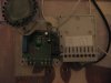
I have included a picture of the timer and workings etc.

M1 and M2 are according to the instructions live and neutral
M3,M5, and M4 are for the controlled device.
Please let me know if i need to explain further or better

Any help/advice greatly appreciated.

Thanks
Moremeba
 

Attachments

  • IMG_0592.JPG
    IMG_0592.JPG
    810.9 KB · Views: 462
Are you expecting to receive power from M3,M5, and M4? They look to me like just the contacts where you have to provide power to them.

With no power applied, you should read zero ohms between M3 and M5.
 
Hi thanks for the reply. according to the instructions M3, M5 and M4 are for the controlled device. m3=normally closed contact, m5=common m4=normally opened contact.
I am not sure i understand when you mention that these contacts should have power supplied to them....i thought that power came to these contacts through the timer to control the device....in my case a water pump.
I hope i have explained this correctly.
Thanks again
Moremeba
 
The diagram clearly shows to the experienced person that it the contacts are not connected to the control circuit. It is the users responsibility to supply power to the contacts. If you want to switch 240V e.g. you would attach 240V LINE to M2, and to the wiper M5.

The LINE of your N.O. load would be connected to M4. The NEUTRAL of your load would be connected to M1.
 
Hi again, i am wanting to switch 240 volts to a water pump. Are you saying that i put the (input) live to m2 and neutral to m5? and the water pump(output) live to m4 and neutral to m1?

Thanks
Moremeba
 
Hi, is there anyone else that can help with this, i`m getting desperate to install these now.
Thanks in advance
moremeba
 
Lets deal with the screw terminals on the case and not the PCB.

Line Hot to #2
Line Hot to #6
Line Neu to #3
Pump Neu to #3
Pump Hot to #a

I'm assuming the timer's relay is rated to handle the starting current of the pump motor. It looks like 16A/240VAC form their web site.

Ken
 
Thanks KMoffett, i will try in the morning and let you know how i get on. I assume when you say LIne Hot to 2+6 you mean live to 2 and stick a jumper wire to 6?

Thanks again
 
Actually, I would do a "live" to 6 and a jumper (small wire) to 2. Terminals '6' and 'a' have to carry the high pump current.

Ken
 
Status
Not open for further replies.

Latest threads

New Articles From Microcontroller Tips

Back
Top