Continue to Site

Welcome to our site!

Electro Tech is an online community (with over 170,000 members) who enjoy talking about and building electronic circuits, projects and gadgets. To participate you need to register. Registration is free. Click here to register now.

  • Welcome to our site! Electro Tech is an online community (with over 170,000 members) who enjoy talking about and building electronic circuits, projects and gadgets. To participate you need to register. Registration is free. Click here to register now.

Help to identify a fuse.

Status
Not open for further replies.

elmariatche

New Member
Hi fellows!

This is my first incursion in the electronic world and I'm really necessitating you help with an issue. I'm a doctor (anesthesiologist), so completly numb in this area . But i'm a curious person and I'm trying to repair a baby monitor cam with a micro usb power socket that came of the board.

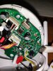
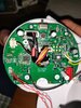
What happen? I plugged a new micro usb socket to a compatible charger and tried, without soldering yet, to put it in place on the board, just to check if I was having electrecity throught the board. The cam came on and was working just fine. But in a fraction of a second it turned off and I could see a little bit of smoke coming from the upper right side of the board. (see attached photos, please). Since that, the camera looks dead.

In there any blowed fuse that I can replace? Where is it?

Thanks for you patience and time.
 

Attachments

  • IMG_20200416_235913.jpg
    IMG_20200416_235913.jpg
    1.7 MB · Views: 99
  • IMG_20200416_232743.jpg
    IMG_20200416_232743.jpg
    2.1 MB · Views: 102
Welcome to the forum. I see something at the upper right side of the board labeled F1 on the silkscreen between Q17 and ZD1 just to the right of the slide switch S2. I don't see a value on the fuse Looks like DN or ON on the top. The F label is usually a fuse. Put the test leads of an ohm meter across that and if it is a good fuse there will be almost zero resistance and if it is blown it will be open circuit.
 
Welcome to the forum. I see something at the upper right side of the board labeled F1 on the silkscreen between Q17 and ZD1 just to the right of the slide switch S2. I don't see a value on the fuse Looks like DN or ON on the top. The F label is usually a fuse. Put the test leads of an ohm meter across that and if it is a good fuse there will be almost zero resistance and if it is blown it will be open circuit.
Pic to aid in locating:

ETO Baby Mon.png
 
Hi doctor,
I too think once you get smoke its all over for the device.
However as a quick check you could solder the usb socket back on, then bridge the fuse with a pair of long nose pliers temporarily, and see if anything happens.
 
Thank you very much for your replies!! The amount of smoke was almost imperceptible. That's why I was hopping it wasn't the famous genie escaping. A fraction of a second did it last... Like a fuse blow. And then... Silence! haha

Apparently, it gives me an open circuit resistance like. Later today I will try what you are suggesting, bypassing the f1 (fuse?) and will come back here to give you an update.

Thanks
 
Its ok as a quick test however permanently bypassing the fuse isnt a good idea.
 
Yes, off course!! That's why he is there. And gess what? He did his job!!
I did exactly what you did and... Doctor, like when a good CPR is performed... it came back to life!! :cool: Dr Pepper rules!!

Now I have to solve another problem... In no way in this world the solder stays in the PCB (40/60, solder paste applied, iron tip as clean as possible) . I think it has been overheated in a way like only newbies know how to do!! Mess like a pro!

Really don't know how I will fix that socket...
 
looks easy enough to put back on put flux on the pads clean them up, resolder the pads then solder on the usb socket. if not and the pads have gone, scrap some of the trace back and solder to the trace.

if you cant do that make your own traces from the next solder point with wire.
 
First off, a fuse like that might be hard to get, you might be able to replace it with a standard 20mm fuse, you could solder wires to each end and solder them to the board, its a tricky job as the fusewire in the fuse can break doing this, putting the whole thing in some tubing to insulate it is a good idea.

And the socket, I would solder it back on without caring if the connections bridge, then come back with some desoldering braid to clean up and remove the shorts.
If you cant manage it the oiutside 2 connections are the power, you could hard wire the power supply direct to the camera, permanently attaching the power supply lead.

Glad to have helped.
 
Status
Not open for further replies.

Latest threads

New Articles From Microcontroller Tips

Back
Top