Continue to Site

Welcome to our site!

Electro Tech is an online community (with over 170,000 members) who enjoy talking about and building electronic circuits, projects and gadgets. To participate you need to register. Registration is free. Click here to register now.

  • Welcome to our site! Electro Tech is an online community (with over 170,000 members) who enjoy talking about and building electronic circuits, projects and gadgets. To participate you need to register. Registration is free. Click here to register now.

Help sourcing two resistors

hotrodjohn71

New Member
Hi group.
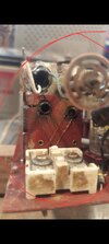
Can you help me source 2 resistors I need for my 57 Ford truck radio?
Ive searched for about a half hour but am coming up short.

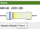
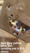
One is a 680k 20% 1/2 watt
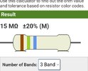
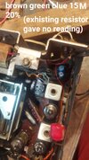
And one is 15M 20% 1/2 watt

Thank you
 

Attachments

  • Screenshot_20240628_145518_Samsung Internet.jpg
    Screenshot_20240628_145518_Samsung Internet.jpg
    81.2 KB · Views: 129
  • Screenshot_20240628_145553_Samsung Internet.jpg
    Screenshot_20240628_145553_Samsung Internet.jpg
    123.7 KB · Views: 98
  • Screenshot_20240628_143413_Adobe Acrobat.jpg
    Screenshot_20240628_143413_Adobe Acrobat.jpg
    404.2 KB · Views: 130
  • 20240628_134603.jpg
    20240628_134603.jpg
    2.1 MB · Views: 124
  • 20240628_141125.jpg
    20240628_141125.jpg
    2 MB · Views: 150
Here are some photos of the tuner unit when I removed it to change the wax/foil capacitors underneath it

I take alot of photos when I work on things.
.
It has 3 'tanks' that have shafts that simultaneously go in and out driven by a worm drive gear from the tuning shaft.

Its hard to see all tanks from any single photo.

the big top tank has a green and white wire which is supposed to be 13 ohms.

otherwise, there are a group of about 5 or 6 tabs that govern the other tanks which solder into the main board.

It was said in the video I referenced earlier that they were factory tuned.
 

Attachments

  • Screenshot_20240705_083710_Gallery.jpg
    Screenshot_20240705_083710_Gallery.jpg
    1.3 MB · Views: 99
  • Screenshot_20240705_083648_Gallery.jpg
    Screenshot_20240705_083648_Gallery.jpg
    1.2 MB · Views: 117
  • Screenshot_20240705_083523_Gallery.jpg
    Screenshot_20240705_083523_Gallery.jpg
    1.2 MB · Views: 87
  • Screenshot_20240705_083445_Gallery.jpg
    Screenshot_20240705_083445_Gallery.jpg
    1.2 MB · Views: 122
  • Screenshot_20240705_093914_Gallery.jpg
    Screenshot_20240705_093914_Gallery.jpg
    1 MB · Views: 102
Last edited:
Here are some photos of the tuner unit when I removed it to change the wax/foil capacitors underneath it

I take alot of photos when I work on things.
.
It has 3 'tanks' that have shafts that simultaneously go in and out driven by a worm drive gear from the tuning shaft.

Its hard to see all tanks from any single photo.

the big top tank has a green and white wire which is supposed to be 13 ohms.

otherwise, there are a group of about 5 or 6 tabs that govern the other tanks which solder into the main board.

It was said in the video I referenced earlier that they were factory tuned.
The "tanks", those are tuning inductors. They are a wound coil, with a ferrite slug that is slid up and down as the operator changes the frequency.
Oh, I did find that signal generator is modulated with 400 cycles.
1720228713733.png


The three tanks are shown in the schematic (note the dash line with M3 label, that has the dash shown between L1, L4, L5 these are all tuning inductors) Those three 'tanks' are inductors. The upper left of the schematic is the antenna input. The first tuning inductor is L1, the signal goes to the grid of V1, which is indicated as an RF amp, that signal is fed to the converter, tube V2, which has another of the coupled tuning inductors on the input to amplify the RF radio channel input, as well what is called a local oscillator, that L5 tunes. This is a frequency that changes with the input frequency, so that the difference frequency created by the converter will be 262.5kilo cycles. That signal is fed to V3, and is labeled as IF AMP. That goes to a tuned transformer L7 to a diode detector labeled as V4 DET-AVC (automatic volume control).
V4 is a dual function tube, as the other section is the AF AMP Audio Frequency amp.
 
Here are some photos of the tuner unit when I removed it to change the wax/foil capacitors underneath it

I take alot of photos when I work on things.
.
It has 3 'tanks' that have shafts that simultaneously go in and out driven by a worm drive gear from the tuning shaft.

Its hard to see all tanks from any single photo.

the big top tank has a green and white wire which is supposed to be 13 ohms.

otherwise, there are a group of about 5 or 6 tabs that govern the other tanks which solder into the main board.

It was said in the video I referenced earlier that they were factory tuned.
My advice as a real RF technican/tv repair guy in the past. Don't mess with them. If the caps change didn't fix the unit then you look at signals with an oscilloscope. But this is after you verified voltages.

But before you connect a scope to it, check the resistance rating of the IF transformers (L6 and L7). The tuning core slugs should be glued in place and tuned where they are at. The only things that go wrong with them is a winding shorted or the capacitors in series or parallel have gone out of tolerance and de-tuned it. Sometimes, they put these capacitors in the IF transformer and you have to take off the metal housing on the IF transformer to access them.
The tools normally used to fix these is an oscilloscope and a 100M VTVM and a signal generator is only used to fine fine tune it.
 
Thank you drtechno.

I still did not solve the issues by changing those resistors as was supposed and infact, the old resistors appear to be within 20% tolerance when checked when removed (as was also supposed).

I think the amplification aspect of the radio is working because I am able to get a little static by poking around the circut board with the power on and the static reacts to the tone adjustment and the volume function, but thats about it.

Unfortunately, I do not have an oscilloscope, and that kind of diagnosis is something I am not acclimated to, not that I couldnt learn eventually.
Well an o-scope is pretty cheap now these days . I got one off amazon for $220. But one thing I should ask you, because its a new guy repair thing, do you have an antenna connected? Because I doubt you will pick up anything without one.
 
As someone who comes from the valve days, and has decades of professional repair experience, an oscilloscope is only VERY, VERY rarely needed for repairing valve equipment. In this articular case it would be a very poor option, and be of next to no use.

It's a simple circuit, basically you need an Avometer (or any similar analogue meter - although a digital one would do as well), a screw driver and a finger :D

If you're really pushing technology, a simple transistor multivibrator would be useful, as an AF/IF/RF signal injector.

First job, with screwdriver and finger, buzz the top of the volume control - to check if the audio stages are working. Then check all the voltages on the valves.
 
As someone who comes from the valve days, and has decades of professional repair experience, an oscilloscope is only VERY, VERY rarely needed for repairing valve equipment. In this articular case it would be a very poor option, and be of next to no use.
Signal analysis is usually the last troubleshooting method to apply. Especially when voltage measurements don't reveal the problem. This holds true regardless if its tube or solid state.
 

Latest threads

New Articles From Microcontroller Tips

Back
Top