Electro Tech is an online community (with over 170,000 members) who enjoy talking about and building electronic circuits, projects and gadgets. To participate you need to register. Registration is free. Click here to register now.
Welcome to our site! Electro Tech is an online community (with over 170,000 members) who enjoy talking about and building electronic circuits, projects and gadgets. To participate you need to register. Registration is free. Click here to register now.
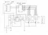
I am in the process of trying to draw up a multiplexed display .
I am having trouble with the circuit
I would like to use the parts I have listed in the circuit digram on the attachement.
It is a up counter to 99 then reset.
Help.
There is no counter IC, the mux is a data select and your inputs are floating, you have to demux it to drive encoder then decoder driver for display. Well you don't have to demux it most of the time.
I will look into some. What is wrong with using a ripple counter or a cascading counter???
For mux displays:
2) 74192 counters, 1's counter and decade counter
1) 555 Timer
1) 74157 to 7447 decoder driver
1) free running clock, pulse, logic switch, etc (another 555 astable pulse can be used here)
All the inputs are used on the mux. I didn't use any transistors on my project display.
This site uses cookies to help personalise content, tailor your experience and to keep you logged in if you register.
By continuing to use this site, you are consenting to our use of cookies.