Continue to Site

Welcome to our site!

Electro Tech is an online community (with over 170,000 members) who enjoy talking about and building electronic circuits, projects and gadgets. To participate you need to register. Registration is free. Click here to register now.

  • Welcome to our site! Electro Tech is an online community (with over 170,000 members) who enjoy talking about and building electronic circuits, projects and gadgets. To participate you need to register. Registration is free. Click here to register now.

Help! PWM signal emulator! How do I make one?

Status
Not open for further replies.

mytmousemalibu

New Member
I want to see about making a Pulse Width Modulated signal emulator controller!

Heres the skinny on the application, info, etc.

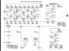
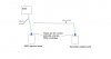
This is for an automotive 12 volt system. What it spicificly is, is for adding a dual common-rail injection pump on a Duramax. It has a solinoid valve on it that is PWM controlled from a 0-5v signal. To add a dual pump, I cannot just tee into the existing wires, as it would devide the signal and run the pumps at too high of psi. So an emulator needs to be used to copy the original signal! Now, there are aftermarket avalible kits but there way to expensive for what it is. I'd rather learn somthing, save some money, and get the satisfaction of building my own stuff:D

As for my electronics experiance, im pretty green! I have a DVOM, soldiering gear. I have done some minor PCB work, like replace a capacitor, relay, and fix ring-breaks. SO not much experiance.

Can you folks help me build one? Think this might be a great project, just explain everything to me! Im new to it all!

Thank You!
 
Your best bet is with a microcontroller. Since your new to electronics I would try a microcontroller kit, try the arduino line. You'll need to do a lot of reading, but it's not a hard first project.
 
Ok great! Thank you! Now what kit should i get from them and what is it that i need to read?
 
If anyone else has some advice, tips & tricks, links, lemme know!

Keep the info comin! It is most appriciated!
 
To add a dual pump, I cannot just tee into the existing wires, as it would devide the signal and run the pumps at too high of psi. So an emulator needs to be used to copy the original signal!
So both pumps are driven with the same 0/5V PWM signal. Why can't you 'tee' it? Have you tried connecting it?

I imagine the voltage won't be reduced much. If it truly is (and if it actually affects the performance), then you can use a buffer to 'copy' the original signal and feed it into the other pump. You can use an opamp (capable of 0V output) or a CMOS 555 or CMOS buffer (or inverters), et al.

I have a DVOM, soldiering gear.
If you put your soldiering gear on, it'll probably help.:rolleyes:
 
Thanks for responding! I havent personally tried to just tee the pumps, but im positive it wont work. It is of course why there are dual pump control boxs. The pump itself is purely mechanical. Now the fuel is metered by the FCA, fuel control actuator, that is PWM regulated, moving a slide valve inside. The FCA is a VERY finicky solinoid and even a tiny drop in voltage will ramp up the rail pressure up approx 2000psi. With 2 pumps that would iirc guys said they had almost 10,000 psi !!!

Can you explain the buffer details more for me! And as for the rest too, im pretty clueless about all this stuff!
 
I know nothing about trucks or fuel pumps. If you could draw a quick sketch of the system you plan to implement (include signals), it would be helpful for me to understand what you're trying to do.
 
Sure! I'll have to do that tomorrow though, I need to get to bed! Thank you for your help! Ill get back to you tomorrow ;)
 
Something doesn't make sense... what is the "controlling signal", the PWM duty cycle or the voltage? There must be some sensors somewhere for feedback...
 
Sorry im just now getting back to ya guys, bad weather last night ended my internet access, good old satellite for ya!

And yes, my apology, it is duty-cycle (PWM) controlled. My tuning software shows it as so. Now, I know for a fact that i cant just splice in to the existing wires to control the 2nd pump.

The fuel rail pressure sensor gives the ECM an indication of fuel pressure. The ECM uses this information to regulate fuel pressure, by commanding the fuel pressure regulator open or closed on the inlet of the fuel injection pump.

i made a crappy paint pic and a OEM diagram:eek:
 

Attachments

  • FCA diagram.gif
    FCA diagram.gif
    60.7 KB · Views: 452
  • dual fuel.jpg
    dual fuel.jpg
    31 KB · Views: 266
It doesn't make sense to me why you cant use the same pwm signal for both solenoids. The ECM will read the pressure signal and back off on the pwm duty cycle as the pressure increases. Unless the system would get unstable somehow by adding another pump (which is possible - I would assume it was designed for a single pump) the control signal must back off as the pressure increases which means both pump valves would be restricted at the same time. Adding a second pump will just increase the rate of pressure build up which would mean less on time for both pumps. I suppose you could get an overshoot on the pressure but what other signal would you be able to use to control the second pump?
 
From your drawing, seems the ECU provides the actual "driving PWM" signal to the pump (maybe that's why it's sensitive to changes in the driving voltage). Perhaps the ECU doesn't have the "balls" to drive two in parallel so maybe all's you need is a "buffer/driver". Aside from that, OutToLunch's aguments are all valid.
 
Thanks Fellas!

Ya, even me lookin at the diagram, and beenings it a PWM signal, it would seem possible to tap into the existing wires. I didnt think of that OutToLunch, I think your right! The OEM system was never designed for 2 pumps. IIRC there are 4-5 or more companys that make the "Dual Fueler" kits, as there called. They all have a "box" that splits the signal to run the 2 pumps, whats in there boxes, no idea. I remember asking if i could just tie into the orig wires, and they all said no, too much psi. It could very well be an instability issue lookin now, ECM cant keep up fast enough?

Im not entirelly positive but is/couldnt the PWM signal, although a duty cycle, be 0-5v variance? If so, in my head it still kinda seems like that signal getting chopped in 1/2, would still split the voltage down? Or dosnt matter?

One other thought i had is that maybe the aftermarket boxes in these kits are intercepting the return signal to the ECM and are cheating/adjusting the signal back? Maybe tricking the ECM into thinking theres too much PSI so its output signal is correct for 2 pump operation?
 
I forgot!

Like said, the pump is purely mechanical, The only part electric on it is the 2-wired, duty-cycle controled fuel pressure regualtor (FPR). So its the only thing controlling the actual fuel psi. The ECM looks at other things, like the fuel psi sensor, and coolant temp and TPS signal and such to calculate the needed psi and hence demand the FPR to the desired position. The FPR is: Max fuel psi= low duty cycle / Low fuel psi= high duty cycle. Like if i unplug it while the engine is running, the pump creates max pressure.
 
Status
Not open for further replies.

Latest threads

New Articles From Microcontroller Tips

Back
Top