Continue to Site

Welcome to our site!

Electro Tech is an online community (with over 170,000 members) who enjoy talking about and building electronic circuits, projects and gadgets. To participate you need to register. Registration is free. Click here to register now.

  • Welcome to our site! Electro Tech is an online community (with over 170,000 members) who enjoy talking about and building electronic circuits, projects and gadgets. To participate you need to register. Registration is free. Click here to register now.

Help please

Status
Not open for further replies.

railroadtime

New Member
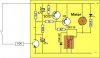
OK here is my problem: I want to control a 1.2vdc motor remotely.
I have a device that I can remotely close a set of contacts and I got a latching relay with 2 “C” type contacts ( ASX2101H from Digi-Key)that I can remotely latch UP with that remote contact closure.
My problem is I have to reverse the polarity on the ASX2101H relay to un-latch it (knock it down). I have been racking my brain trying to figure out how to use the same remote contact closure to latch and un-latch the relay. I have a couple of ASX2201H relays coming from Digi-Key in the hope that with enough relays and contacts I might be able to do it.
Could anyone give me some help here please?
Everything is using 1.2vdc AA batteries.
Any help sure would be appreciated.

Thanks
Neil
 
I have a circuit that uses a single output to turn your motor on and off. But it uses a normal relay.
 
Here's the circuit:

**broken link removed**


The circuit allows a single channel transmitter/receiver to turn an appliance on and off by sending a short pulse to turn a circuit on and a long pulse to turn a circuit off.
This is handy when you cannot see the result of your operation. A simple toggle operation is not suitable as you do not know the state of the output at the start of the operation.
By sending a long pulse, you definitely know the output will be OFF and you can then control the output remotely.
A short pulse is less than 0.25 sec and a long pulse can be any length longer than 1 second.
 
Last edited by a moderator:
Ah yes you have a single coil latching relay in the 2101. There are also dual-coil types that sometimes make it easier.

Dave Johnson has a nice little circuit that works for boosting voltage to a dual-coil latching relay:
Circuit Solutions, Ultra Low Power Latching Relay Circuit by David Johnson P.E.

But anyway for single coil Omron has an application note showing a simple circuit that might be useful. I found it like this:
go to this link:
Digi-Key - G6SU-2-DC4.5-ND (Omron Electronics Inc-ECB Div - G6SU-2 DC4.5)
and find the "other related dcouments" link "Relay Technical Overview". Click that relay technical overview link.
scroll down to page 16 of the .pdf and find the section called
"Designing Power-conserving Driver Circuit with Single Winding Latching Relay"
this shows how to toggle such a relay on and off with a single input. Their circuit is simple and clever.
 
Thanks Colin55 and RadioRon, for the good information, it helps. I’m still struggling with it but it looks like it is possible, I just need to put it all together.
I thought I had it yesterday but it didn’t work like I thought it would. Now I need to go through it to see if I wired something wrong or the idea is flawed.

Neil
 
Here is the Patented circuit to pulse a latching relay on and off via a single line:


**broken link removed**


You can check the operation by replacing the relay with two back-to-back LEDs and a series 150R resistor.
 
Last edited:
colin55,
If I set this up like this diagram (I hope the diagram comes through), insert a plug in the jack and momentarily short the Tip and Sleeve remotely with a button, will I be able to lock the relay up and down with the momentary short?
Do I have the polarity reversed?
Thanks
Neil
 
Last edited:
The way the circuit works is this:

Supply a voltage to the circuit, say 12v.
The initial current-flow is large and it gradually drops to about 1mA.
You must keep the 12v supplied to the circuit.
Now, when the 12v is removed, the circuit produces a reverse-voltage to the relay that unlatches the contacts. This reverse voltage is produced INTERNALLY (within the circuit) by the electrolytic and transistor.
 
If you look at my second link, you would find a useful theory of operation of this circuit.
 
That is all good information but not quite what I’m looking for. What I want is: a pulse to latch the relay up (power on, then off), then a while later, say ½ hr, another pulse to un-latch the relay.
These designs show the relay latching when the power is applied and un-latching when the power is removed ie
Set
When a specified voltage is applied
across E, the current flows through the
circuit in the sequence of diode Di1,
capacitor C, relay Ry, and diode Di2.
C is then charged, setting the relay.
Reset
When the voltage placed across E is
removed, the electricity charged in C is
discharged, causing the current to flow
through the circuit in the sequence of Rb,
the base, and the emitter of TR. In this
way, the relay is reset by the current
flowing in the direction opposite to when
the relay is set.

What I am looking for is when the voltage is applied and removed, the relay is latched up, when the voltage is applied and removed again, the relay is un-latched.

I’m not very knowledgeable about this stuff, just enough to be dangerous.

Maybe I won’t be able to get it to work the way I want.

Anyway, thanks for all your help.

Neil
 
What I am looking for is when the voltage is applied and removed, the relay is latched up, when the voltage is applied and removed again, the relay is un-latched.


Neil

You can adapt the circuits mentioned above to what you want by adding a flip flop. A flip flop can be wired to divide a pulse stream by 2. What this means is that every time you provide one complete pulse, that is, low....high...back to low.... the output of the flip flop will change state from low to high or from high to low, depending on where it was before the pulse came along.
Check out the first diagram in this link:
**broken link removed**
Notice that when the "input frequency" goes from low to high, the output frequency changes state.
 
Do you want to operate the relay from a distance?
Do you want to be sure it is SET or RESET?
Can you see its activation?
 
Then use the first circuit I presented. It works with a long and short pulse.

A HIGH for a short time or a HIGH for a long time. Simply remove the integrating stage.
 
Last edited:
Colin55,
I am going to try the first circuit you posted but I can’t tell what is to the left of the circuit, especially the transistor in the lower left that is only partially there. Is there a better circuit available?
I think that may be what I’m looking for.
Thanks
Neil
 
You need the "half-transistor" and connect a 10k resistor to the base and drive the base through this resistor.
 
Last edited:
Is this what it would look like? Remember I'm in way over my head here so I may be way off base.
Is that a BC557 transistor and is that resister that is marked 4k7 a 4k ohm resister?
Thanks for all the help.

modified-ckt-2-jpg.26796
 

Attachments

  • Modified ckt 2.jpg
    Modified ckt 2.jpg
    27.2 KB · Views: 188
Last edited by a moderator:
Status
Not open for further replies.

Latest threads

Back
Top