Continue to Site

Welcome to our site!

Electro Tech is an online community (with over 170,000 members) who enjoy talking about and building electronic circuits, projects and gadgets. To participate you need to register. Registration is free. Click here to register now.

  • Welcome to our site! Electro Tech is an online community (with over 170,000 members) who enjoy talking about and building electronic circuits, projects and gadgets. To participate you need to register. Registration is free. Click here to register now.

HELP PLEASE! barrier/door control panel trouble

Status
Not open for further replies.

tufdog71

New Member
I know this is off the wall. I've been repairing overhead doors for 20+ years and have always been able to isolate and troubleshoot electrical/wiring problems. Until this week. I got saddled with a self-storage account that has very old access control technology. I can't find a manufacturer or installer, and the site manager is no help.

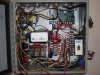
The roll-up doors and barrier arms are connected/synchronized through a separate "control panel". This panel is where my problem is. I have already isolated the barrier and the door and tested all functions of each independantly without issue. It's whan evverything is connected together that I am having timing problems or faults.

The concept for the system is pretty simple: keypad to open the roll-up door (goes through computer to grant access), door open limit triggers barrier to open, 2 separate timers-to-close (one for barrier, one for door) with two ground loops wired in-series as safeties. Thats the entry door. The exit door is slightly different....it has free-exit loop to open, everything else is the same.

I need some help identifying which relays control which functions in this panel. On the exit door, I managed to stumble across a missing limit switch, and...VOILA!...the barrier arm now works, the timing is correct, and no problems.

I tried to upload 3 photos of the panel in question. It didn't work. I will be glad to e-mail the photos to anyone willing to try to help. I DO HAVE a clear sketch of the wiring terminal strip labels (which are obscured by the spaghetti explosion of wires). I don't have a wiring diagram.....I think I'm gonna have to make one.

Anyone who has more to offer than, "Quit while you're ahead!" is much appreciated. I don't like giving up, but I know I'm in over my head here. If the switches are all good, then it has to be a relay problem? How do I isolate it? Should I just replace all 3 relays and hope for a miracle?

The entry door motor gear reducer blew a seal and the oil leaked out. I replaced the door motor with a current UL-325-2010 compliant (Liftmaster GH1043-L4) one with a logic board control, and now I have a problem. ...................................................

Somehow I am ending up with a "maintained" close command, which after 2 minutes the door operator recognizes this as a "fault" and won't work unless i pull the close wire off the terminal. And I can't live at this place.

Thanks for reading!
 
the new operator is L4 logic. I called Liftmaster tech support after I determined that the close command is apparently maintained and asked why I was having this problem. . They said that L4 logic recognizes a maintained command after 2 minutes as a "fault/stuck button". And won't respnd to any commands until the button is "un-stuck" (take the wire off the terminal).

This is why I need help with how the colse command gets to the door operator from the relays in the junction panel. I had to return to the site this morning for a "NO OPEN". The logic board indicated a "stuck open". WHich is very odd. THere haven't been any issues sice I opted for the Timer-to CLose feature on the L4 board.

Maybe I should just replace the 3 12vdc 4PDT KH ice cube relays. They may be original, and after 10+ years of hi-cycle door use could be wearing their contacts out or hanging up intermittently.

I would still appreciate any help in understanding how this junction panel actually works. This customer has 3 sites with these panels and I don't see myself escaping this nightmare anytime soon!!
 
It sounds like the issue is the "maintained" state. Does the motor control logic "prefer" a pulse to change state: open<->close?

If so, use a 555 with a capacitor in series from the relay output to the 555 trigger. Either state edge (H->L or L->H) makes the capacitor pulse, triggering 1 crisp pulse out of the 555. Pulse duration can be whatever you want and 555s operate 4.5 -> 16 volts. Somewhere between 1 and 10uF should be enough to trigger it.

I'm understanding just enough of this to not know if I can help... <<<)))

P.S. just tried Liftmaster link with GH1043-L4: no result.
Also, is there one relays' output for open/close as versed with 2 motor control inputs: separate open & close? If so, I'll need polarities & pulse widths involved to provide a complete answer, but happy to do so.
 
Last edited:
When I looked briefly at the Close logic, some versions used a pulse and others a maintained contact and it seemed like you were not able to change it, a priori. You had to buy the proper logic controller.

Making your own 555 timer ckt does't make sense. A commercial pulse generator or equivelent would be a better way to go. Take a look at www.ssac.com.
 
Last edited:
Point well taken, KISS. Fixing commercial stuff is better addressed with purchased components, not homebrewed. I've been building for so long, it's a kneejerk reaction I should consider more carefully... <<<)))
 
unfortunately due to UL-325-2010 change, the Logic 4 is the only logic available. The previous door operator was an "analog" style....contactor, relays, limit switches. Quite simple if you ask me. But the safety standards have changed. This may just be a case of incompatible circuitry.

I'm sure the maintained contact is at odds with the L4 board.....it throws the board into a fault. I have to look at the wiring and draw a diagram. It's the only way I'm gonna solve this. I will post a photo and a rookie's attempt at a diagram in a few days.

Thanks for reading and offering some advice. I know I'm in over my head, but I'm determined to solve this problem even if I have to create a solution!!!!!!!!!!!!!!!!!!!!!!!
 
So, you know you have a continuous contact system and a momentary board. Easy to fix. What do you have to work with?

12 VDC on close.
Dry contact closure on close?
Power available?

It really looks like you are in a position where you have to create the "glue logic" to make the new controller fit and that's probable where you should be. Hopefully it just won't be a band-aid. A modern interface panel composed of DIN rail and associated components wouldn't hurt.
 
Last edited:
Thanks KISS. One thing I'm sure of is that the customer will NOT spend any money modernizing their building. Which I mentioned, and it was not received well. The panel was installed in 1998 or 99 when commercial door operators were all analog.....no circuit boards. the maintained "close" was overridden by "momentary "open" (which was run through the safety reverse relay).

To answer your questions, the motor operator voltage is 460v/3 phase supply with 24vac controls. The sequence panel is 115vac supply, transformed to 12vac and run through a rectifier for 12vdc. The OPEN, CLOSE, and SAFETY relays are 12vdc.

I'm definately up for trying a pulse timer for the close. I will look at the link you sent. I will also try to upload a photo and my sketch of the terminal strips. I expect to make a courtesy visit later this week, and I will draw a wiring diagram as best i can.
 

Attachments

  • ESS 1197 panel.JPG
    ESS 1197 panel.JPG
    2.6 MB · Views: 184
Somebody need to learn how to design a control panel. Maybe I should find a pic of one of mine. For one, the broke rule #1. DIN rail construction. Rule #2: All inputs should terminate to terminals first. Then everything ranches out. Rule #3: Use of wiring duct.

You will be surprised on just how much neater the system would be. A neater system means it's easier to troubleshoot too.

I had the misfortune that my panel had to be expanded big time. The method of expansion was a low and high voltage conduit connecting the two boxes. Two devices needed low current 120V power. Then a barrier bus was placed in the old cabinet and a similar one in the new cabinet. This is basically similar to the way telephone is done in a large building. The connecton between the two panels is in esscence similar to a "riser" and the blocks inside the "cross connects".

I had to be conservative on space, so I used SPDT dual coil voltage 24 VAC/DC relays that took up maybe 1/4" wide of space. Lamps were replaced by LED lamps. And some nmanufacturer, remains nameless caused me to totally switch to IDEC. The idiots put an "O" ring and encapsulated the heat from the bulbs and broke the plastic holding the lenses. Their old design worked fine. They went tin the history book. They were unwilling to listen to me. I probably had a hundred of their lamps/swiches - not any more.
The second box was mostly empty. It had to hold 2 air velocity alarms. The upgrade happened becaise of an explosion.

Other parts of the system, PLC based, went to a generator backed up UPS system. It could not loose power.

Still others was on a 24 VDC battery backed up system, BUT parts were allowed to go offline for 2 minutes before the generator started.

Macromatic has relays that can do a one-shot thing too and you might have better deliverability. See: https://www.newark.com/jsp/search/b...e=en_US&catalogId=&prevNValues=500003+1000975
 
KISS, I agree 100%. This panel sucks. space is limited and the wires are hard to trace. Not to mention the 460 vac line that feeds the barrier gate runs right through this panel (how did that pass electrical inspection?).

I looked at the macromatic timers. Would the "maintained" close command from the panel cause a timer to "cycle"?

Do I want a "single shot" "control switch" model (product # TR-51526**, page 61) to activate the door operator close command (pulse)? And is the panel close command wired in as the control switch or is the control switch the output to the door operator? I'm confused.

Thanks again for your time and your suggestions.
 
Here is an instruction sheet for that timer. https://www.macromatic.com/search/product/instructions.php?search=t&product=TR-51526-22 I do believe that 6 sec may be too long. You want a single shot timer. Probably 1-5 seconds.

Problem is, I don't know what you have to operate the relay. If it's a dry (voltage less) simple contact closure, your in. If not, let's say it's a 12 V signal that stays high when the gate is supposed to close. Then you would need two relays. The first would isolate, the 12 V signal.

That's why I asked what do you have available or made available?

a) 12 V on close? If 12V, can you convert it to a closure?
b) A dry contact closure on close
 
Last edited:
i'm not sure if voltage is present at the close output terminals. I think it's a dry contact, but I'll have to test it next time I'm there.

as for what voltage(s) is(are) available inside the panel: 115 VAC, 12 VAC, 12 VDC
 
Status
Not open for further replies.

Latest threads

New Articles From Microcontroller Tips

Back
Top