Continue to Site

Welcome to our site!

Electro Tech is an online community (with over 170,000 members) who enjoy talking about and building electronic circuits, projects and gadgets. To participate you need to register. Registration is free. Click here to register now.

  • Welcome to our site! Electro Tech is an online community (with over 170,000 members) who enjoy talking about and building electronic circuits, projects and gadgets. To participate you need to register. Registration is free. Click here to register now.

Help on LED Brightness sign

Status
Not open for further replies.

Selp44

New Member
Hello,
I am no electrician, but i think i can manage a small project like this.
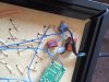
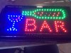
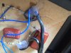
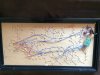
I was given an LED bar sign and its way too bright. I want to reduce the brightness by maybe adding a resistor in line with the 120V or somehow modify the circuit shown in the pics. Any help will be greatly appreciated.
Thanks
 

Attachments

  • image.jpg
    image.jpg
    880.4 KB · Views: 215
  • image.jpg
    image.jpg
    1.5 MB · Views: 206
  • image.jpg
    image.jpg
    757.2 KB · Views: 179
  • image.jpg
    image.jpg
    877.5 KB · Views: 180
Does the electronic circuit board cause some LEDs to blink on and off so it looks like motion? Then if you add a huge resistor that will get VERY hot to reduce the brightness then the blinking and motion might stop.
 
Welcome to the forum!
Without our knowing what's on the circuit board and its intended function it's difficult to advise.
 
Sorry,
I forgot to mention that there are indeed some leds that blink.
I am not sure whats on the circuit board as everything is glued. I could probably take it apart and see whats on there. I was hoping that i could add a potentiometer or something that would help reduce the overall flux intensity of the leds. They are almost blinding..

Does the electronic circuit board cause some LEDs to blink on and off so it looks like motion? Then if you add a huge resistor that will get VERY hot to reduce the brightness then the blinking and motion might stop.
 
U need to isolate the common anode (or cathode) for the LEDS. Then determine the peak current draw....ammeter. Let's say its 2Amps and the system is common cathode.

You need an Nchannel MOSFET ( of perhaps 5A or better rating, in line (Source/drain) with the cathode line) to be gate driven by a 555 chip with a potentiometer to adjust the PWM duty cycle of the pulses. A logic level MOSFET will allow the circuit to run on 5V supply. A regular MOSFET will require a 12 to 18 V supply to switch properly.

Then you can tweak the brightness as you require.

Now IF the LEDS are laid out in serial fashion (your pic indicates this is so) and are using 120V (rectified) to drive them like old Xmas tree lights you shouldn't tamper with it unless you're very competent. the same basic principle will apply, but the FET will have to be rated for the Voltage and current.
 
It looks to me like the circuit has two separate capacitor limited transformerless supplies.

If so, I would repeat that all of it should be regarded as potentially at lethal voltages.

I think that the larger capacitor controls the current to the LEDs. If so you could try putting a capacitor in series with the existing capacitors.

The capacitor should be a bit smaller than the existing one. It must be non-polarised, and rated to 400 V or more. It is a good idea to put a 1 MΩ in parallel with the capacitor, just the same as has been done on the existing one. The resistor will discharge the capacitor within a few seconds when the circuit it turned off. Without it, the capacitors could stay charged for ages.
 
Yes two capacitor limited transformerless supplies,
One for the steady on LEDs and the other going to a DC light sequencer board to flash the others.
It looks like a 3 channel Christmas light controller with a COB but it is DC.
The hole thing looks really cheaply made.
Are all the LEDs to bright?
 
Perhaps a regular light dimmer (chopper triac) would do the job safely then....the LEDs would get less time at the necessary voltage and you have a coarse 60Hz PWM.
 
Perhaps a regular light dimmer (chopper triac) would do the job safely then....the LEDs would get less time at the necessary voltage and you have a coarse 60Hz PWM.

I wouldn't recommend a regular light dimmer. With one of those, each time the triac turns on, there will be a current surge as the capacitor charges. As the triac turns on 120 times a second on 60 Hz supplies, that could damage the circuit.
 
In a transformerless supply, the capacitor is the main current limiting device, so there would be a surge when it turns on. The current would be almost the same as if the capacitor were in parallel.
 
I have a variable transformer. (auto-transformer) With a 110V input I can get 0 to 130 out. That will set the brightness on your sign.
**broken link removed**
 
The surge is limited by the voltage drop of the LED semiconductors in a series arrangement.
There is no surge that matters.

In parallel the surge is only limited by the ESR & ESL of the capacitor which amounts to a short circuit at power up.
 
Assuming we don't want to mess with the input voltage to the controller.
The OP can add series resistance to each string to get the desired brightness.
 
I would simply replace the two capacitors shown in the first image with ones of smaller value, but at least equal voltage rating. Say 1/4 to 1/10 (or less) the existing value, and try to get close to the same ratio for both caps (unless the sequencing LEDs appear brighter or dimmer than the others, in which case using different reduction ratios can be used to balance the brightness.)

This empirical/iterative approach would be simple for me since my workshop is fairly well-stocked with a large selection of capacitors available. But if you don't have a variety of capacitors on hand with suitable voltage ratings, someone else may suggest a better approach.
 
Status
Not open for further replies.

New Articles From Microcontroller Tips

Back
Top