Continue to Site

Welcome to our site!

Electro Tech is an online community (with over 170,000 members) who enjoy talking about and building electronic circuits, projects and gadgets. To participate you need to register. Registration is free. Click here to register now.

  • Welcome to our site! Electro Tech is an online community (with over 170,000 members) who enjoy talking about and building electronic circuits, projects and gadgets. To participate you need to register. Registration is free. Click here to register now.

help on extending infra red data transmission

Status
Not open for further replies.
Hi, thanks to those that helped me with my 9v problem the other week...

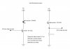
I've built my infra red transmitter - receiver although it works it does so very poorly!!

The range that it can transmit and receive is only a few cm for data transmission! I would like to extend this to a couple of metres if possible?? If anyone can see a way of modifying my cicuit to do so could you please let me know

Thanks again
 

Attachments

  • infra_red_transmitter_receiver.jpg
    infra_red_transmitter_receiver.jpg
    21.9 KB · Views: 385
There are a couple ways to increase the range of your system. Probably the eassiest is to find a photo transistor with more active area. This will increace the amount of light hitting the detector. I'm not sure how much active area you can get on a phototransistor but you can get photodiodes with a fair amount.

Next thing to try is add another gain stage to your receiver. Put an op amp in to amplify the output from the transistor.

If those fail try a lens to focus more light onto your detector.

Finaly you could replace your LED with a Laser and use a lens to spread the beam out to cover the area your receiver will be in.

Hope this helps
Brent
 
Thanks....

Put two infra led's in circuit in series that seems to help a little, think i need to use a more powerfull transistor to increase the current to the led's to get a stronger transmission signal but unsure of the type i will need to use..

Put in a photodiode instead of the phototransistor this helped extend the range to, am now up to a metre and a bit although the application i would like it for would only require this distance i would like to get a signal to the other side of the room several metres away.

Thanks for your help

Carl
 
You need an amplifier on the receiver, the photo-transistor isn't intended to be used on it's own, it's intended to feed a high gain amplifier. To get good range it can be quite complicated, it's usual to modulate the beam and only amplify the received modulation - this avoids problems with ambient light etc.

The usual modulation fequency is about 40KHz, and you can buy small three pin receiver IC's which do everything - simply providing a high or low output. These easily work at 10-20 metres. For the transmitter you could use a simple 555 oscillator.
 
Thanks, i've started to connect up a 734 amp to the receiver end, i shall see how this improves things.... Am a little unsure about the modulation on how to modulate the signal in particular!

Carl
 
carlosthejackle2001 said:
Thanks, i've started to connect up a 734 amp to the receiver end, i shall see how this improves things.... Am a little unsure about the modulation on how to modulate the signal in particular!

You simply turn it on and off, 40,000 times a second. If you look at 555 circuits you need the astable mode, just a simple flasher - but at a faster rate.

If you look at my PIC tutorials at http://www.winpicprog.co.uk you can see how I do both the transmit and receive ends using PIC's in the IR tutorial.
 
I think my encoder chip pulses the transistor on and off at 3khz as this is what i have set the oscillator at and the decoder is set 50 times that of the encoder at aprox 150Khz...... maybe am wrong in thinking this!??
 
carlosthejackle2001 said:
I think my encoder chip pulses the transistor on and off at 3khz as this is what i have set the oscillator at and the decoder is set 50 times that of the encoder at aprox 150Khz...... maybe am wrong in thinking this!??

I'm sorry, I don't understand that at all?.

Why would you operate at different rates, how could it possibly work?.

Also, what do you mean by your encoder and decoder, all you showed on the diagram was an LED and a photo-transistor.
 
i showed where the input was comming from its a data enoder chip, its a "HT12E" and the decoder on the receiver end is a "HT12D" at the output.

Baisicaly a 12 bit code is transmitted, the reciever checks that the first 8 bits match with its preset 8 bit code and if they do then it allows the other 4 bits of the 12 bit code through as data.

The data sheets give a formula to set the oscillators differently on each chip.

Sorry for the confusing am new at building things practically and find it tricky to explain things clearly.

Carl
 
carlosthejackle2001 said:
i showed where the input was comming from its a data enoder chip, its a "HT12E" and the decoder on the receiver end is a "HT12D" at the output.

Use an HT12A, not a 12E, the 12A is designed specifically for IR and feeds 38KHz out to the LED. On the receiver side use an IR receiver IC to feed the decoder IC, these are simple 3 pin devices which do everything for you.
 
Status
Not open for further replies.

Latest threads

New Articles From Microcontroller Tips

Back
Top