Hi Firends, 
I am building a Ni-Cd charger to be given to Tsunami victims for their pocket FM radios. I have designed the ckt but would like to know whether it is ok before I actually attempt to build it. Please see the below description and the circuit and give me your views/ideas. Sorry it is little long....
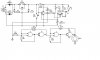
The center tap transformer (T1), Diodes D2,D3 and IC7806 will supply the power to the circuit. Two Ni-Cd’s are been charged by a constant current source based on PNP transistor BD140 (Ic-max 1.5A, V max 80V, P max 12.5W) which is controlled by a voltage comparator LM393.
While the cells are being charged, out put of the comparator is low and the transistor is ‘on’. LED will now glow indicating that cells are being charged. Once the cells are charged to their 80% or more capacity, their terminal voltage rises to about 1.45volts, the trigger threshold of the comparator which is set by R3 POT at around 2.9 volts (1.45 X 2), exceeds the output of comparator goes high. Now the transistor is ‘off’ and charging ceases.
The capacitor C3, controls the comparator toggling, when the battery voltage is too low. Once the charging ceases, the e.m.f of the battery drops almost instantly. This might cause the charging circuit to be switched on again, resulting in a charging voltage rising to the level set with R3. To prevent this oscillatory condition, the capacitor across the comparator enables the battery to stabilize. If after a short delay, the battery voltage proves to be too low, the current is switched on again. The capacitor then assures that the current will flow for a while, irrespective of the battery e.m.f. Can a feed back resistor be used to get the same results?
Switch S1 can set between 15 ohms and 6.8 ohms resistors to have 14 hours and 5 hours (fast charge) respectively. The reference voltage for constant current source is obtained from the forward voltage drop of the LED, which is around 1.5 volts for a red LED. V(BE) for a Si transistor is around 0.65 volts. Then voltage drop across R2 or R7 is V (LED) – V (BE). This is 0.85 volts. Thus formula for charging current becomes 0.85/R2 or R7. With R2=15 ohms, the current is around 57mA or 125mA if R7=6.8 ohms. Is this sufficient for a AA size cell of 600 mA to charge 14 hours or 5 hours?
In order to have a audio indication, the high logic state of the comparator is fed to the CMOS IC 4011 B to make a pulsed-tone alarm.
I am building a Ni-Cd charger to be given to Tsunami victims for their pocket FM radios. I have designed the ckt but would like to know whether it is ok before I actually attempt to build it. Please see the below description and the circuit and give me your views/ideas. Sorry it is little long....
The center tap transformer (T1), Diodes D2,D3 and IC7806 will supply the power to the circuit. Two Ni-Cd’s are been charged by a constant current source based on PNP transistor BD140 (Ic-max 1.5A, V max 80V, P max 12.5W) which is controlled by a voltage comparator LM393.
While the cells are being charged, out put of the comparator is low and the transistor is ‘on’. LED will now glow indicating that cells are being charged. Once the cells are charged to their 80% or more capacity, their terminal voltage rises to about 1.45volts, the trigger threshold of the comparator which is set by R3 POT at around 2.9 volts (1.45 X 2), exceeds the output of comparator goes high. Now the transistor is ‘off’ and charging ceases.
The capacitor C3, controls the comparator toggling, when the battery voltage is too low. Once the charging ceases, the e.m.f of the battery drops almost instantly. This might cause the charging circuit to be switched on again, resulting in a charging voltage rising to the level set with R3. To prevent this oscillatory condition, the capacitor across the comparator enables the battery to stabilize. If after a short delay, the battery voltage proves to be too low, the current is switched on again. The capacitor then assures that the current will flow for a while, irrespective of the battery e.m.f. Can a feed back resistor be used to get the same results?
Switch S1 can set between 15 ohms and 6.8 ohms resistors to have 14 hours and 5 hours (fast charge) respectively. The reference voltage for constant current source is obtained from the forward voltage drop of the LED, which is around 1.5 volts for a red LED. V(BE) for a Si transistor is around 0.65 volts. Then voltage drop across R2 or R7 is V (LED) – V (BE). This is 0.85 volts. Thus formula for charging current becomes 0.85/R2 or R7. With R2=15 ohms, the current is around 57mA or 125mA if R7=6.8 ohms. Is this sufficient for a AA size cell of 600 mA to charge 14 hours or 5 hours?
In order to have a audio indication, the high logic state of the comparator is fed to the CMOS IC 4011 B to make a pulsed-tone alarm.