tazman171
New Member
Hey there, I'm doing a lab for my digital concepts class and already 1 day late (was due friday) with it.
I can only use these parts: 3 7400 quad NAND gates, 2 7402 quad NOR gates, 1 7493 counter chip, 7446 BCD-7-segment decoder, 1 7404 hex inverter gate, 3 7432 quad OR logic gate, 1 7486 quad XOR gate, 7-segment led display, resistor packs for the leds.
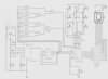
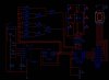
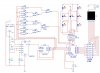
My circuit is all nand with no inverters using 3 7400Ns, 1 7493 counter chip, 1 7493N, 1 555 Timer, 1 7447 BCD decoder and 7-segment led display. There are 7 leds representing the face of a die, labeled T,U,V,W,X,Y,and Z. Z = a 1 roll, T + Z + Y = a 3 roll with T at the top left and Y at the bottom right.
I can get it to roll and stop on random numbers when I hit the key that starts and stops it but I can't get the counting right. A 6 on the die is a 0 on the 7-segment display, a 1 is a 3, etc.
I'm attaching a 7zipped multisym 11 file and a picture of the circuit. If the truth tables are needed I'll post them too.
Edit: White background image added
Thanks for any suggestions.
I can only use these parts: 3 7400 quad NAND gates, 2 7402 quad NOR gates, 1 7493 counter chip, 7446 BCD-7-segment decoder, 1 7404 hex inverter gate, 3 7432 quad OR logic gate, 1 7486 quad XOR gate, 7-segment led display, resistor packs for the leds.
My circuit is all nand with no inverters using 3 7400Ns, 1 7493 counter chip, 1 7493N, 1 555 Timer, 1 7447 BCD decoder and 7-segment led display. There are 7 leds representing the face of a die, labeled T,U,V,W,X,Y,and Z. Z = a 1 roll, T + Z + Y = a 3 roll with T at the top left and Y at the bottom right.
I can get it to roll and stop on random numbers when I hit the key that starts and stops it but I can't get the counting right. A 6 on the die is a 0 on the 7-segment display, a 1 is a 3, etc.
I'm attaching a 7zipped multisym 11 file and a picture of the circuit. If the truth tables are needed I'll post them too.
Edit: White background image added
Thanks for any suggestions.
Attachments
Last edited: