AndersRasmussen
New Member
Hello.
I really need help, as I have to hand in my semester project on friday, which contains a prototype. The prototype is a lamp made for seeing embryos in eggs, and therefore I am working with high power LED's (CXA1304-0000-000C00A40E7 ), 9V ,1A. I am an production engineer , so this is not my normal field of expertise. I just can not seem to figure a soulution to the following problem:
I have made a PCB (see picture 1 and 2).
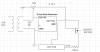
The PCB consist of 6 LED's wired in parallel. Original intention was getting an LED driver, with a dimmer. Unfortunately it got lost in the mail, and I have no time to order a new one. Therefore I kinda fixed it, with stuff I had at home(see wiring diagram, picture 3(and sorry for the very bad schematics, hope that you get what is going on)). The schematics of the PCB can be seen in picture 4.
So my problem is that there is a significant differens in temprature and lux between the LED's placed furthest away from each other. Can I do something to fix this, or shall i just get used to it? I have a feeling that the amps might be playing tricks on me, but i do not have a ampmeter...
The lamps works, and is sufficient for what I am using it for, but I like working with electronics, and therefore would really be happy to learn what is going on.
Any advice or tipsto a noobie who has a deadline in a few days? xD
Thx, and nice day to your all!")
Picture 1 Picture 2


Picture 3

Picture 4

I really need help, as I have to hand in my semester project on friday, which contains a prototype. The prototype is a lamp made for seeing embryos in eggs, and therefore I am working with high power LED's (CXA1304-0000-000C00A40E7 ), 9V ,1A. I am an production engineer , so this is not my normal field of expertise. I just can not seem to figure a soulution to the following problem:
I have made a PCB (see picture 1 and 2).
The PCB consist of 6 LED's wired in parallel. Original intention was getting an LED driver, with a dimmer. Unfortunately it got lost in the mail, and I have no time to order a new one. Therefore I kinda fixed it, with stuff I had at home(see wiring diagram, picture 3(and sorry for the very bad schematics, hope that you get what is going on)). The schematics of the PCB can be seen in picture 4.
So my problem is that there is a significant differens in temprature and lux between the LED's placed furthest away from each other. Can I do something to fix this, or shall i just get used to it? I have a feeling that the amps might be playing tricks on me, but i do not have a ampmeter...
The lamps works, and is sufficient for what I am using it for, but I like working with electronics, and therefore would really be happy to learn what is going on.
Any advice or tipsto a noobie who has a deadline in a few days? xD
Thx, and nice day to your all!
Picture 1 Picture 2
Picture 3
Picture 4
Attachments
Last edited:
") . And yes it's dropping some voltage, but it was the most suitable MOSFET I had around, do you think it is giving me issues?
. And yes it's dropping some voltage, but it was the most suitable MOSFET I had around, do you think it is giving me issues? 