Continue to Site

Welcome to our site!

Electro Tech is an online community (with over 170,000 members) who enjoy talking about and building electronic circuits, projects and gadgets. To participate you need to register. Registration is free. Click here to register now.

  • Welcome to our site! Electro Tech is an online community (with over 170,000 members) who enjoy talking about and building electronic circuits, projects and gadgets. To participate you need to register. Registration is free. Click here to register now.

Help needed with a small comparator/control circuit

Status
Not open for further replies.

BigJohnny

New Member
I got some instructions how to build this circuit from another board, and for some reason they have stopped responding to the thread, and I'm a little stuck here.

What I have is a small digital thermometer for a computer, that uses a thermistor for it's probe.

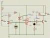
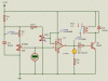
What I want to do is build this circuit to control a replay, so that when the thermometer reaches a certain temp, it will kick on a relay to control a heating device.

Half of this circuit works, the other half doesn't and I don't know why, this is where I'm stuck.

First of all, the trim pot I'm using is a 201XR101B, would the middle pin on this pot be pin 2 in the diagram?? I may or may not have that connected properly. But it does create a variable voltage between 0 -60mV, so it appears to be working, I just want to confirm that pin2 is the middle pin on that pot.

Below is the diagram. The problem I'm having is that no matter how much voltage is coming from vRef, the connection to the relay only ever sees around 4.97v

I think I might have the pins wired wrong on the op=amp so that's where I really need the help.

The op-amp I have is LT1013DIP on the package, so can anyone confirm if the pins are wired wrong, and if they are, how do I need to re-wire them for it to work?

**broken link removed**
 
Hi,

I doubt very much that the circuit does create a reference voltage of 60mV. Use a 1KΩ (instead of 10KΩ) resistor for R5 and the pot value should be 200Ω. The maximum reference voltage will then be 81.5mV. The pot in your schematic is wired correctly.

Also R3 (110Ω) is much too low in value, causing high base current and pulling the output of the comparator below the required base voltage. Use a 5.6KΩ resistor for R3.

Ignore RS1 and RS2 in my schematic. They just simulate the temperature sensor.

If you want to use an LED connected directly to the ouput pin of the IC use a low current LED (If=2mA). Connect a "normal" LED (If=20mA) parallel with the relay and use a current limiting resistor of 560Ω in series with the LED.

Boncuk
 

Attachments

  • COMP01.gif
    COMP01.gif
    10.8 KB · Views: 298
  • COMP02.gif
    COMP02.gif
    10.9 KB · Views: 235
oh, R5 is 1K, I just forgot to update the diagram for that.

so what are you saying the problem is exactly? is the pinout on the op-amp correct? I.E do I have it wired correctly as it is for the op-amp I have (there are 3 packages, the two 8pin packages have different pinouts)

I have measured it, and adjusted it while measuring, the reference voltage is putting out around 60mV at max, and it does indeed decrease when I adjust the pot.


looking at the diagrams, what is the difference between the two?

as I see it, there are now two pots? what is R3(1) and D1(A) etc??
 
Last edited:
so what are you saying the problem is exactly? is the pinout on the op-amp correct?

Just use pin2 for the inverting input, pin3 for the non-inverting input and pin6 for output. +13.5V should be connected to pin7 and ground to pin4.

I.E do I have it wired correctly as it is for the op-amp I have (there are 3 packages, the two 8pin packages have different pinouts)

Pins 1, 8 and 5 are used for offset correction. Leave them unconnected. No same IC has different pinouts for the same package.

looking at the diagrams, what is the difference between the two?

There is a big difference: Diagram1 shows the relay and the LED deactivated, diagram2 shows the relay pulled in and the LED on (bright yellow)

as I see it, there are now two pots? what is R3(1) and D1(A) etc??

I can't help you if you can't read. There are two resistors in the circuit labelled RS1 (fixed value resistor 4.7KΩ) and RS2 (pot 1KΩ). I wrote to ignore them since they represent (simulate) the temperature sensor.

Once again: Ignore RS1 and RS2 in my schematic. They just simulate the temperature sensor.

Heating the monitor won't result in changing circuit behaviour. :)

If you take a close look you will see a V followed by a numeric value underneath (D1(A)=D1(anode)), which is the voltage at that point. U1(+IP) stands for the voltage probe at the non-inverting input and R3(1) is the input voltage probe of R3.

You might understand them as a voltage probe of your DVM.

Boncuk
 
Last edited:
Status
Not open for further replies.

Latest threads

New Articles From Microcontroller Tips

Back
Top