Continue to Site

Welcome to our site!

Electro Tech is an online community (with over 170,000 members) who enjoy talking about and building electronic circuits, projects and gadgets. To participate you need to register. Registration is free. Click here to register now.

  • Welcome to our site! Electro Tech is an online community (with over 170,000 members) who enjoy talking about and building electronic circuits, projects and gadgets. To participate you need to register. Registration is free. Click here to register now.

Help needed on wiring up LED 7 segment number

Status
Not open for further replies.

saber_holder

New Member
Hey all... Right now I'm in the process of building a replica of the Pulse Rifle prop from the movie "Aliens". If your familiar with it, you'll know that the guns have LED shot counters on the side to show how many bullets are left. For my prop, I'm going to put one of these counters in, but I need some help.

Before I start though, I want to say that I'm NOT planning on having these go or cycle in any sort of order.. They will be static, and will stay on the number I want.

So, I go over to my friendly neighborhood Walmart to get some supplies. As usual, they really didn't know what to get for me, but they had some of the parts that I needed. I got 2 of these 1 digit 7 segment LED counters, some wire, and some AA batteries and battery holsters (its what they reccommended to get).

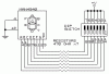
I get home, and I immiediatly start touching the wires to the pins on the LED (don't flame me about shorting lights out.. I know hardly anything about this). Nothing happens. I hope they arn't burnt out. So I go online and start talking to a fellow prop maker who knows some stuff about LEDs. We talk about it for a while, and eventually find this tutorial:
https://www.iguanalabs.com/7segment.htm

We talk about it for a while, and eventually find out that we need to wire each pin to the VCC (with a resistor in between), and then wire the VCC to the positive end of a 9 volt... But heres the problem.. Where does the negative battery power supply go?


Each LED has a wire coming from it... but only one. Where the heck is the negative supposed to go? Thanks.
 
Whoops - not counter, i meant bcd decoder

===============================


Easiest thing to do is to connect it to a counter ic

Put a switch connected to the clk input on the ic to vcc

Everytime you push the switch the lcd will count up a segment ( from 0 - 9 then back to 0)
 
Generally speaking, 7-segment displays are made in two basic versions -- common cathode and common anode. The first thing that you want to do is to determin which type your is. Then, take a look at for a 7-segment display. It should help you get your wired up, as many displays use one or another of the pinouts provided in the datasheet cited. BTW -- that DS is for a 7-segment display with a right-hand decimal point -- yours may or may not have the decimal point... :)
 
The display should have a 'common' pin, the second connection of all leds are internally tied together and connected to this pin...

Also know that leds are diodes so they only work 1 way. If it doesnt work try connecting the battry the other way around...

And indeed, NEVER forget the resistor, connecting the leds to 9V without a suitable resistor will destroy them (+- 470 ohm for each led should do fine)
 
gjpollitt said:
Everytime you push the switch the lcd will count up a segment ( from 0 - 9 then back to 0)

ahem, whatever happened to debouncing?


anyway, if the number will always be the same, you will only need one resistor, however, its value will change, depending on the number of segments being lit up at any one time.
 
grrr_arrghh said:
gjpollitt said:
Everytime you push the switch the lcd will count up a segment ( from 0 - 9 then back to 0)

ahem, whatever happened to debouncing?


anyway, if the number will always be the same, you will only need one resistor, however, its value will change, depending on the number of segments being lit up at any one time.

I didnt go into detail about the circuit, just explaining a brief outline

If required I will design the circuit complete with debouncing and upload it here.

Just giving general pointers, thankyou very much indeed :)
 
Ok.. My kind is Common cathode. I'm aware of the common pin, and how each led needs to be connected to it.. and then through a resistor, and to the positive end of my battery.. I'm still lost on one thing though.. Where does the negative end of the battery go???
 
Every led is connected to a seperate resistor, the ends of all these resistors are connected together and this is connected to the batteries + side.

The common pin on the display goes directly to the battery -
 
saber_holder said:
Before I start though, I want to say that I'm NOT planning on having these go or cycle in any sort of order.. They will be static, and will stay on the number I want.

Here's a simple circuit which will allow you to set the display to whatever number you want without counters, decoders, etc. I use a MAN4940 display (simply what I have on-hand) which is common cathode. If you have a different display (probably), change the pin numbers on the diagram to reflect your display's pinout. If you don't know the pinout for your displays, google the part number, you'll probably find it easily. If your displays are common anode, reverse the battery connections on the diagram.
To display whatever number you want, use the dip switches to turn on the segments you want to light. The resistors are 470 ohm and will allow about 19mA thru each segment with a 9v battery. If you want to use 2 AA cells, change the resistor value to 150 ohm (20mA). If the display is too bright, use a higher value resistor. If you use a lower value, you may damage your displays. JB
 

Attachments

  • dipsw_led.gif
    dipsw_led.gif
    3.9 KB · Views: 987
Jbeng, I think your schematic is the best idea for saber_holder. However, you neglected to account for LED forward voltage, which is nominally 2.2v at 20ma. For a 9 volt supply, a resistor of 360 ohms will give about 19ma. 3 volts seems pretty low to use on a 2.2v LED.
 
Ron H said:
However, you neglected to account for LED forward voltage ...

True, Ron. Thanks for pointing out my error. I do that sometimes. :oops: Last eve, I did hook up one of my 4940's with a 9 volt and a 470 ohm and even at 15 mA, it was pretty darn bright. I probably wouldn't even use the 2 AA's anyway, because a 9v is easier to connect (with it's clip contacts) and it would last a lot longer. JB
 
Status
Not open for further replies.

New Articles From Microcontroller Tips

Back
Top