littletransistor
New Member
Hi,
I constructed my own astable multivibrator circuit with the resistors 2x 360 ohms and 2 x 36K ohms (these are on the bases of both transistors). Transistors: 2x PNP CS9012. The caps are 47 micro farads.
By right it should oscililate, but the whole circuit is dead - so could it be my new breadboard's fault? I tried that combination in a terminal block, and it worked.
Or could it be my connections?
Here's the pic - I tried reconnecting it but still it didn't work. Ooooh.
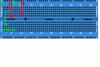
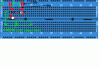
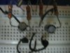

")