Continue to Site

Welcome to our site!

Electro Tech is an online community (with over 170,000 members) who enjoy talking about and building electronic circuits, projects and gadgets. To participate you need to register. Registration is free. Click here to register now.

  • Welcome to our site! Electro Tech is an online community (with over 170,000 members) who enjoy talking about and building electronic circuits, projects and gadgets. To participate you need to register. Registration is free. Click here to register now.

help needed for A HIGH ACCURACY THERMOCOUPLE AMPLIFIER

Status
Not open for further replies.

joshua.svn

New Member
Hi,

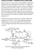
i am giving schematic and all details of A HIGH ACCURACY THERMOCOUPLE AMPLIFIER from analog devises,
but i am not able to understand the isothermal block which is given in diagram below d1- 4148 around.
please give detailed explanation of this block which is simply copper clad on pcb or some thingelse will it get in market ? and google search word for this . i googled but cant find any use full details.

regards
svn.

upload_2014-11-8_21-19-53.png
 

Attachments

  • upload_2014-11-8_21-18-46.png
    upload_2014-11-8_21-18-46.png
    138.3 KB · Views: 269
Last edited:
If you can find a manual for the Fluke 2176a, https://www.testequipmentconnection.com/956/Fluke_2176A.php , it has the best isothermal block I have ever seen.

The connections are massive and there is a silicon sensor. The whole point is you have to measure the temperature of the terminals very accurately (thus a large thermal mass), and you have to do it with a sensor that is accurate.

I've seen a lot of stupid compensation systems form a thermistor in free air to stuff made by analog devices built into a connector.

I have to go, for now, but I might address it later.
 
The voltage measured at the isothermal block depends upon the temperature difference between the ends of the thermocouple wires attached to the isothermal block and the thermocouple tip. It also depends upon ensuring that the ends of both thermocouple wires attached to the isothermal block are maintained at the same temperature. Therefore, as the temperature of the isothermal block changes (with changes in room temperature), the voltage measured at the isothermal block will change even though the thermocouple tip temperature does not change. To compensate for this, the voltage measured by the circuit at the isothermal block is adjusted by relying on the fact that the junction voltage of the 1n4148 diode changes with temperature also.

Edit: For that circuit, the key thing to keep in mind about the isothermal block is that both ends of the thermocouple wires attached to it and the diode are kept close to each other so as to be at the same temperature. Aside from that, the isothermal block is nothing special unless you are looking for more precision like that found in lab instruments (in which case the circuit design needs to be improved as well). Copper clad on a PCB will do okay for the terminations. I would cover all three with silicon RTV which is an electrical insulator having fairly good thermal conductivity.

Edit: Something that may not be understood from the diagram has to do with the screw terminal connections shown outside the outline of the isothermal block. Unless the wires connected between the screw terminals and the isothermal block are extensions of the same type of wires used in the thermocouple, the screw terminals must be part of the isothermal block, otherwise additional unwanted thermocouples are formed. In other words, the screw terminals should BE the isothermal block terminals.
 
Last edited:
ccurtis:
Your explanation is a bit confusing, but suffice to say that Thermocouples depend on temperature differences and are highly non-linear/ The tables depend on a having the reference junction in an ice bath and measuring the difference between two thermoucouples.

The connections at the isothermal block are known as half-junctions and you want them to have the same change with temperature, Hence, isothermal.

The compensation circuit may only be valid for a certain range of ambient temperatures (The temperature of the block).

You need:
An isothermal connection and the exact temperature of that junction, called the reference junction.
You need the measured voltage difference.

Using software, you can tailor the parameter that you need.
(1) You need the voltage that would be measured at the 1/2 junction temperature as if the reference is 32 F (from the tables)
(2) You need the voltage difference between the two 1/2 junctions (one at the TC and one at the measuring element)

From those numbers and some polynomials, you can determine temperature.

This https://www.mccdaq.com/usb-data-acquisition/USB-TEMP-Series.aspx was one of the worst performers for TC measurements. It did fine with RTD's. All it took was a fan blowing on top of the terminals and the output was wrong.
 
Last edited:
Read this link as it provides a simple overview of using thermocouples for temperature measurement. As suggested, also Google and read up on CJC (Cold Junction Compensation) because that is what the D1 you question is all about. D1 is a 1N4148 everyday diode. Nice thing about diodes is they can be used as temperature sensors. Take a look at the 1N4148 data sheet. The diode's Vf (Forward Voltage Drop) will change depending on the diode's junction temperature. By wiring a diode and resistor in series (Look At Your Drawing) between a power source and ground the Vf of the diode can be measured across the diode. The diode is placed on a thermal block where the dissimilar alloy thermocouple leads (Alumel and Chromel) are connected to the Cu (Copper ) wires. Note what happens in this situation in the first link I posted, see figures 4, 5 and 6 in the link. So what D1 is doing is compensating for the cold junction temperature.

Ron
 
Status
Not open for further replies.

Latest threads

Back
Top