Continue to Site

Welcome to our site!

Electro Tech is an online community (with over 170,000 members) who enjoy talking about and building electronic circuits, projects and gadgets. To participate you need to register. Registration is free. Click here to register now.

  • Welcome to our site! Electro Tech is an online community (with over 170,000 members) who enjoy talking about and building electronic circuits, projects and gadgets. To participate you need to register. Registration is free. Click here to register now.

Help need to create Digital Control Fan Remote Controll

Status
Not open for further replies.

manojsoorya

Member
Hi good evening everybody...
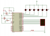
I have circuit and i want to change some connection in this circuit.......

My recomedation is as follows

When the Dispaly is 0, only the LED 1 ON
When the Dispaly is 1, the LED 1 and 2 ON
When the Dispaly is 2, the LED 1,2 and 3 ON
When the Dispaly is 3, the LED 1,2,3 and 4 ON
When the Dispaly is 4, the LED 1,2,3,4 and 5 ON
When the Dispaly is 5, the LED 1,2,3,5 and 6 ON
and again the Dispaly is 0, only the LED 1 ON

I am not familier to programe or write the code....

So i need a help from somebody

Please help me and thank you everybody


Hope a god hand on my work....


Thanks
 

Attachments

  • Fan Display.png
    Fan Display.png
    48.4 KB · Views: 377
  • fan Display.txt
    560 bytes · Views: 325
You just need to create another table to store the LED data.

DB 1, 3, 7, 15, 31, 63

Then do the same to access each element. Each of these will bring on the correct number of LED's

Each time the button is pressed Increase R0.. When it equals 6 then reset it to zero.. R0 can be used to access the digit table AND the LED table...

But i dont know to write the code.....I get this from web...can you help me to write the code?


Code

ORG 00H
START: MOV DPTR,#TABLE ; Moves a 16-bit data to the data pointer
MOV R0,#00H
MOV P0,#3FH
MOV P2,#3FH ; initial display count 0
S1: INC R0
CJNE R0,#6,S2 ; switch press 6 then reset display to 0
MOV R0,#00H
S2: JB P3.7,$
LCALL DELAY
JB P3.7,S2
S3: MOV A,R0
MOV B,#10
DIV AB

MOVC A,@A+DPTR
MOV P0,A
MOV A,B
MOVC A,@A+DPTR
MOV P2,A

JB P3.7,S1
LJMP S3

DELAY: MOV R5,#20
D1: MOV R6,#250
DJNZ R6,$
DJNZ R5,D1
RET

TABLE: DB 3FH,06H,5BH,4FH,66H
DB 6DH,7DH,07H,7FH,6FH
END

****************************

what the change may i do in this code?
 
You'll have to wait for later.... I will help you when I get home from work..


thank you master...Now my time is here : 10.00 PM... I wait for your reply as soon as possible...I am here upto 02.00 AM for your reply....

Thank you for your valuable help, God bless you allways...
 
No.... I don't respond to mail... I have too many as it is.

Code:
START:				
		MOV		R0,#00H		
		MOV		P0,#0FEH
		MOV		P2,#3FH 		; initial display count 0
		
MAIN:	MOV		DPTR,#DIGITTABLE
		JB		P3.7,MAIN
		INC		R0				
		CJNE		R0,#6,PASS		; switch press 6 then reset display to 0
		MOV		R0,#00H
PASS:	MOV		A,R0
		MOV		B,A
	
		MOVC	A,@A+DPTR	
		MOV		P2,A
		MOV		A,B

		MOV		DPTR,#LEDTABLE		
		MOVC	A,@A+DPTR
		MOV		P0,A
		LCALL	DELAY100
		LJMP		MAIN


DELAY100:	MOV		R4,#50
DELAY10:	LCALL		DELAY
		DJNZ		R4,DELAY10
		RET

DELAY:	MOV		R5,#20		
D1:		MOV		R6,#250
		DJNZ		R6,$
		DJNZ		R5,D1
		RET		

DIGITTABLE: 	DB 		3FH,06H,5BH,4FH,66H
		        DB		6DH,7DH,07H,7FH,6FH
LEDTABLE:	DB		0FEH,0FCH,0F8H,0F0H,0E0H

		END

I had to invert the LED table as I'm sinking the LED's instead.
 
Hello Master Ian Rogers.........

First I thank to you for your humble help co change the assmbly code......Thank you very much and god bless you always

Your code 100 and 100 % of working........ :)

Faithfully Manoj Soorya
 
No.... I don't respond to mail... I have too many as it is.

Code:
START:				
		MOV		R0,#00H		
		MOV		P0,#0FEH
		MOV		P2,#3FH 		; initial display count 0
		
MAIN:	MOV		DPTR,#DIGITTABLE
		JB		P3.7,MAIN
		INC		R0				
		CJNE		R0,#6,PASS		; switch press 6 then reset display to 0
		MOV		R0,#00H
PASS:	MOV		A,R0
		MOV		B,A
	
		MOVC	A,@A+DPTR	
		MOV		P2,A
		MOV		A,B

		MOV		DPTR,#LEDTABLE		
		MOVC	A,@A+DPTR
		MOV		P0,A
		LCALL	DELAY100
		LJMP		MAIN


DELAY100:	MOV		R4,#50
DELAY10:	LCALL		DELAY
		DJNZ		R4,DELAY10
		RET

DELAY:	MOV		R5,#20		
D1:		MOV		R6,#250
		DJNZ		R6,$
		DJNZ		R5,D1
		RET		

DIGITTABLE: 	DB 		3FH,06H,5BH,4FH,66H
		        DB		6DH,7DH,07H,7FH,6FH
LEDTABLE:	DB		0FEH,0FCH,0F8H,0F0H,0E0H

		END

I had to invert the LED table as I'm sinking the LED's instead.


when i burn chips, a message will appear....what it does mean?
the message is
Error:
Address:0
Buffer: 78
Device: ff
Is it any programe error?
 
Last edited:
I really don't know... I used to use Phillips chips not Atmel... They had bootloaders in so I never had that issue...

What program software and what hardware are you using?


I am using the Atmel Chip. The programer I am used in this company...(Please check this link below)

**broken link removed**


and I am using the software for simulation......

First I simulate in proteus 7 then use topview to again simulate. The two simulation are ok, the hardware 100% working.. In one of the simulation is not correct, the hardware maynot work.


In our proteus simulation was OK, But in Topview simulation not correct. In Topview simulation, the LED 5 not working at the time of Display 5.
when the display show 5, all LED are off (inactive). Not more error.
If you want the TOPview executable file, i give you the link.

I wait your reply when you are get free time.

Thanks

Manoj Soorya
 
Last edited:
I hope you put current limiting resistors on the LED's


Usually, If it works on ISIS then it works for real... Did you put a pullup resistor on the button?

Hi Master

I dont use current limiting resistors on the LED's and not use pullup resistor on the button. That is the problem?

Thank you...verymuch
for your kindness
 
I hope you put current limiting resistors on the LED's


Usually, If it works on ISIS then it works for real... Did you put a pullup resistor on the button?

Hi Sir,

First of all, the programme was correct but my programmer was faulty now. So i need to buy another universal programmer an i contact you latter...

Hope you help me again...

Thank you very much

Manoj Soorya
 
I really don't know... I used to use Phillips chips not Atmel... They had bootloaders in so I never had that issue...

What program software and what hardware are you using?

Hi Master..
The problem is in my programmer....Now i buy a new one and its working....But I dont get the correct output.
But the simulation is 100 % OK..But i build the circuit, its has some error
mean....when the 5 th LED not active when the Display shows the number 5....any idea?
Thank you
 
Give me time to re-read the thread and find my working out.... It's been a couple of months..

Thanks to respond my request Master..

I fixed the problem and circuit is 100% correct output....Thanks.......
I did this way...

I am just add

{DIGITTABLE: DB 3FH,06H,5BH,4FH,66H
DB 6DH,7DH,07H,7FH,6FH
LEDTABLE: DB 0FEH,0FCH,0F8H,0F0H,0E0H,000H}

Then its clear....Thank you master.....Bye
 
Status
Not open for further replies.

Latest threads

New Articles From Microcontroller Tips

Back
Top