Electro Tech is an online community (with over 170,000 members) who enjoy talking about and building electronic circuits, projects and gadgets. To participate you need to register. Registration is free. Click here to register now.
Welcome to our site! Electro Tech is an online community (with over 170,000 members) who enjoy talking about and building electronic circuits, projects and gadgets. To participate you need to register. Registration is free. Click here to register now.
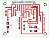
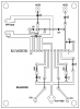
Can you help me to say after seeing the circuit design whether my circuit design of KIA6283 Audio Amplifier is correct or not ? Please tell your views about it to rectify my error !
Why don't you use the pcb design shown on its datasheet?
EDIT: You are using low frequency electrolytic capacitors for C6 and C7 but the datasheet says to use high frequency polyester film capacitors. So your circuit will probably oscillate at a high frequency.
As my PCB is not working at all as there is no sound present. I think I have done some mistakes in designing. As I am using realPCB of Crocodile Technology software where some sort of features is unavailable so it made these mistakes as well as my ignorance about circuitry. I am habituate with realPCB but not in any other PCB software. I am self-taught in PCB design. So may I have some weakness in this matter. If you can rectify it as I will be very much happy about your generosity.
You never told us how you are connecting all the grounds on your pcb together so I guessed that you are using a double-sided pcb with the ground connections all on one side and most of the circuit that you showed on the other side.
Then I guessed correctly.
You should use the shematic, pcb design and thick traces used on the recommended pcb design shown on the datasheet for the amplifier ICs.
Then I guessed correctly.
You should use the shematic, pcb design and thick traces used on the recommended pcb design shown on the datasheet for the amplifier ICs.
This site uses cookies to help personalise content, tailor your experience and to keep you logged in if you register.
By continuing to use this site, you are consenting to our use of cookies.