Continue to Site

Welcome to our site!

Electro Tech is an online community (with over 170,000 members) who enjoy talking about and building electronic circuits, projects and gadgets. To participate you need to register. Registration is free. Click here to register now.

  • Welcome to our site! Electro Tech is an online community (with over 170,000 members) who enjoy talking about and building electronic circuits, projects and gadgets. To participate you need to register. Registration is free. Click here to register now.

Help mostfet switch not turning off

Status
Not open for further replies.

mitchjs

New Member
Hi all...

I'm using

https://www.electro-tech-online.com/custompdfs/2006/02/FDV304P.pdf

and i need logic 0 to turn on the mostfet (which it does)
and 3.3 volts to turn it off (which it doesnt)

im trying to switch 5v

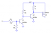
its source is connected to 5v, its gate is pulled to 5v though 47k, and then connected to logic via 1k

so.. i need the drain to be at 5v when gate is 0 (<1) and 0v when gate is 3.3 (>2.7)

im a bit confused...

i could use a pnp trans too, prob need a zener on the base, but i dont understand how that works, i have seen it, and wouldnt know what voltage to use

thanks!
mitch
 
A Mosfet will turn off when its gate voltage is the same as its source voltage. This Mosfet is turned on a little with only 0.65V for its Vgs.
 
Your problem is that the voltage on the Gate is not high enought to switch the FET off. There are a few possible solutions.

1. Do you have a higher voltage (regulated) available, (6 or more volt)?

2. If not, then you could insert a 3.3 Volt Zener (cathode to Gate) in series with the 1k resistor. However, I would reduce the 1k to 100 Ohm.

3. You could use a PNP transistor with 2 resistors and a 3.3 Volt Zener.

Tell me which option you want to use and I'll do the calculations for you.
 
audioguru said:
A Mosfet will turn off when its gate voltage is the same as its source voltage. This Mosfet is turned on a little with only 0.65V for its Vgs.
Yes, but that is the minimum.

The maximum is 1.5 V so you would need to ensure that Vgs is > 1.5V when the FET is to be on and < 0.65V when it is to be off.
 
mitchjs said:
lets do the pnp and a zener

I want to use B856 (got them)

mitch
Rather than a Zener, I suggest you use 2 red LEDs in series (anode to base) Connect a 270 Ohm resistor to the logic output and a 10k resistor between base and emitter.

You did not say what load current is.
 
leds, i dont know if that will work

i think the logic can only sink 4ma


my load is <20ma on the transistor

mitch
 
mitchjs said:
leds, i dont know if that will work

i think the logic can only sink 4ma

my load is <20ma on the transistor

mitch

The current through the LEDs will be about 2.6 mA when the output of the logic is at 0 V. So they may glow faintly.

The transistor will easily source the load current.
 
just so i know, how does this work?

is there a way with a zener?

i went ahead and soldered in a bc856

E to 5v, C to my load, B pulled to 5v though 10k

waiting on how to connect b to my 3.3v logic

mitch
 
Hi Mitch,
A PNP transistor will have the same problem as a P-channel Mosfet when the input voltage is less than the supply voltage. It won't turn off.
 
i know that...

can i put a series zener on the base?

like a 2.7v zener?


so, microcontroller 3.3logic to 1k r, to zener, to base of pnp


mitch
 
A zener diode won't boost 3.3V to 5V.
Why not use the same supply voltage for everything to avoid requiring a level-shifter?
 
Here's a couple of more ideas...
 

Attachments

  • pmos_dvr.png
    pmos_dvr.png
    8.9 KB · Views: 453
mitchjs said:
i know that...

can i put a series zener on the base?

like a 2.7v zener?


so, microcontroller 3.3logic to 1k r, to zener, to base of pnp


mitch
Why are you having a problem with the LEDs?

I used LEDs in lieu of a Zener because low voltage Zeners do not have a sharp "knee".

You could use a single Blue LED in lieu of the 2 Red ones.

The point of the LED or Zener is to switch off the base current when the input is high.
 
audioguru said:
A zener diode won't boost 3.3V to 5V.
Why not use the same supply voltage for everything to avoid requiring a level-shifter?
Audio, You are missing the point. When the input is at 2.7 V, the voltage across the Zener (or LED) will be 5 - 2.7 = 2.3V.

Thus a 3.3 V Zener would have only a small current through it. As I said in the previous post, low voltage zeners do not have a sharp "knee" so that I why I prefer the LED solution.

I suggest you do a switcherCAD simulation (as I did). With 2 red LEDs or a single blue one, the collector current is <1uA when the input is at 2.7V.

Edit. I just re-checked it. It is 3.3 * 10 ^ -10
 
Hi mitchjs,

I would vote for the "non-inverting" circuit suggested by Ron as it can provide the near 0-5V drive signal to the P-ch MOSFET, resulting in the least Rds upon turn ON.
 
eblc1388 said:
Hi mitchjs,

I would vote for the "non-inverting" circuit suggested by Ron as it can provide the near 0-5V drive signal to the P-ch MOSFET, resulting in the least Rds upon turn ON.

Yes, I agree provided that mitchjs is happy with a non inverting solution.

However, he specified that he wants the circuit respond to <1V, so Ron's circuit needs a diode or red LED in series with the base in order to ensure this.

And, as I told Ron in a PM, his other solution needs a diode in series with the base as Q1 will not be fully off at the specified 2.7V.
 
ok, now im getting more confused

if i put a 2.7v zener in series with base, it does work

so your saying the tansistor is slightly on...

which is ok, cause its way less then a volt conducting through trans

mitch
 
mitchjs said:
ok, now im getting more confused

if i put a 2.7v zener in series with base, it does work

so your saying the tansistor is slightly on...

which is ok, cause its way less then a volt conducting through trans

mitch

What I said is that low voltage Zeners don't have a sharp "knee" and I can't find a decent data sheet for a either a 2.7V or a 3.3V Zener so I can't calculate whether a Zener is adequate.

Also, my SwitcherCAD simulation software does not have a model for either of these Zener values, so I can't check it by simulation.

You also need to consider thermal effects. If the transisor is partially on at a temperature of say 20C, then it will be even worse at 30C since Vbe decreases with increasing temp.

However, I do have SwCAD models for both a red LED and a blue one. Both of these (ie. 2 red or 1 blue) give satisfactory operation.
 
That noninverting circuit I posted will work, after a fashion, if you adjust some of the resistor values. The problem is, it doesn't account for the resistance of the logic stage driving the input. It would be better to just use two inverters, as below. There are probably other solutions which are as good or better.
 

Attachments

  • pmos_dvr2.png
    pmos_dvr2.png
    5.9 KB · Views: 290
Status
Not open for further replies.

Latest threads

New Articles From Microcontroller Tips

Back
Top