Continue to Site

Welcome to our site!

Electro Tech is an online community (with over 170,000 members) who enjoy talking about and building electronic circuits, projects and gadgets. To participate you need to register. Registration is free. Click here to register now.

  • Welcome to our site! Electro Tech is an online community (with over 170,000 members) who enjoy talking about and building electronic circuits, projects and gadgets. To participate you need to register. Registration is free. Click here to register now.

Help identifying some diodes

Status
Not open for further replies.

Serafis

New Member
Hi from New Zealand.

I'm attempting to repairing a Pioneer PDP-50MXE1 plasma display, with a failed power supply. I've identified the area of failure (blown IC MIP3E3) but am having trouble identifying some diodes that have been damaged (physically and electrically) by the burnout.

Does anyone know where I can find a schematic of the PSU board (AXY1083), or can anyone help identify the following through-hole diodes, or suitable substitutes?

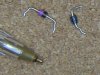
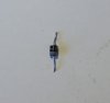
Diode D141: plastic, marked with a double cathode band and "B3710", then in smaller numbers "45".

Diode D133: plastic, marked "06" along the body, then "47" at right-angles i.e. around the body. Or if I read it upside down, the first numbers could be "90".

Diode D205: glass, marked 24B2. I think this is a 24V 1/2W Zener - can I use a 24V 1W zener (e.g. 1N4749) to replace it ?

Diode D149: plastic, marked "Z150 4.D" - is this a 150V 1W Zener?

Diode D139: epoxy, marked "Z100 4.1", is this a 100V 1W Zener?

Any help most gratefully appreciated.

Thanks in advance, Jon.
 
Welcome to ETO!
You might be able to confirm if any of them are zeners by looking at the board marking, commonly you get a different diode symbol or a "ZD" rather than just "D".
I've been having a look to try to find a manual. There are other PDP models here which may be sufficiently similar for your needs: https://www.manualslib.com/
The lack of datasheets on the web suggests they are in-house part numbers.
I would suggest that D141 is an ultrafast or other special type, due to having a double cathode band.
You should look for other clues on the board, like what the diodes are connected to, voltage ratings of capacitors, etc, manufacturers suggested circuits for any chips connected may also give you a clue.
Hopefully we have someone here who knows Pioneer gear and can be more help!
 
Thanks, unfortunately all the diodes are just marked "Dnnn" on the PCB, and the service manual for this panel doesn't include a schematic of the PSU.

The blown IC is marked MIP3E3 - it's a 7-pin DIP and according to the only datasheet I can find with any English on it (most are Japanese), is a "Silicon MOSFET type Integrated Circuit - For a Switching Power Supply Control" with DRAIN Voltage 700V and Control Voltage 8V. Pin's 1,2,3 and 8 are Source, Pin 4 is Control and Pin 5 is Drain - it's the Drain pin that has melted.

Here's a schematic of the area in question (best I could do by following the tracks on the 2-sided board!) with the faulty components circled, and I've also included mockups of the body markings. There are other connections to T104 windings that I haven't been able to trace yet.

Schematic (Medium).jpg

Cheers, Jon.
 
Last edited:
Hmm
I've got a few of those type of 7 leg pwm chips pulled from old PSUs so it's a common enough type of device. Found a data sheet in english straight away http://www.datasheet39.com/PDF/845874/MIP3E30MP-datasheet.html
I'm more inclined to agree with your zener diode theory now I've seen the schema. Though if that is the case they are doing something unusual because there's no limiting resistor. I guess this is where the "specialness" of the others comes in.
Maybe look at standard designs for switch mode supplies for clues. I know very little about them.
Where you've shown diode symbols with 2 cathodes lines, is that the actual marking on the board or is it your own invention?
You could pull the remaining good z100 and z150 and test the reverse voltage to confirm if they are zeners. At this point I don't think you are losing anything if the test proves destructive!
Might be worth testing the Vf of the other dual cathode band one, see if it tells you anything there.
I suspect they have an extra layer inside :confused:
Hope you realise it's slightly possible there's a shorted turn inside the transformer, very hard to spot. Unusual but it happens.
 
The two cathode lines on the schema were my invention merely to remind me about the double band.

Assuming Z100 is a 100V zener and Z150 is a 150V zener (which Google indicates they might be), from looking at various other switchmode schemas, I think the these two in series will be equivalent to a single 250V zener, and put back-to-back with the B3710 across the transformer primary, this combination probably makes a surge protector/transient killer. And while a bit charred by the blast from the melted IC pin, these all seem to test OK on the DMM, with voltage drop across each of them (at 9v, 25mA) 0.79V - same as the good ones elsewhere on the board. So I may just put these all back in and hope for the best.

The other two diodes are shorted. Google tells me that 24B2, which sits between Source and Control on the IC, may be equivalent to NTE5031A, a 24V zener. Another (much simpler) switchmode schema I found with the MUIP3E3 had a 10V zener in this position , although the data sheet for MIP3E3 gives the Control voltage (VC) as 8V, so I'm not sure why this zener would be 24V (or 10V). There isn't another of these on the board to make any measurements or comparisons unfortunately. Anyway, I guess no harm in trying this - it can't be more broken than it is now!

Which leaves the diode which, depending on which way up I hold it, reads "74" at right angles to ""90", or "06" at right angles to "47". There are some others of these on the board near 250V and 280V electrolytics. Voltage drop on these is 0.75V. Maybe another zener, or ultrafast recovery switching, presumably around 200V - any thoughts on this one?

Anyway, thanks for your help so far and any other insights you (or anyone else) have would be most welcome.
 
You're doing pretty well it seems, I admine your perisistence!
You have mis-traced your schematic. Showing D139, D140, D141 and T104 winding all in a closed loop! If you found that part by tracing with dmm perhaps it's indicating a short?
The voltage of D205 probably has something to do with the relative level of the source and drain voltages, and the signal coming in via L104. Does look an odd arrangement though.
As to D133, can you post a photo? If it's a funny shape/colour it's more likely to be an ultrafast recovery diode. Can you post a photo (you can attach direct to post, it's easier for respondents than following a link) of that one? Markings don't usually do something silly, so with the "4" the right way up the rest should make sense. The 4 and the 7 are likely to follow the other two digits rather than come before. They could be some code that isn't part of the part number (like a date code or batch number).
I just looked up this old thread: https://www.electro-tech-online.com/threads/strange-looking-diodes.126721/ but the photo's gone missing. I think this is the one.
 

Attachments

  • odd-diodes.JPG
    odd-diodes.JPG
    104.9 KB · Views: 222
Re the schematic - there are other connections to the T104 winding from other parts of the board, but I haven't managed to trace them yet. The diodes sit in parallel with the winding (like T102) which is why they looked to me like surge/back EMF/transient suppressors.

I'm new to this forum so hadn't noticed you could add photos directly - thanks for that - and have edited the earlier post to show the schematic in-line.

Below are thumbnails of the diodes, showing (left to right) Z100 (D139), Z150 (D149), 74-90 (D133), B3710 (D141) and 24B2 (D205).

P1080989 (Medium).jpeg

The next three photos show D133's markings, cathode at the bottom, rotating the body left-to-right.

P1080990 (Medium).jpeg P1080991 (Medium).jpeg P1080992 (Medium).jpeg

And here's the same, with cathode at the top in case it makes more sense that way round. I can't make head nor tail of it! Hope someone can.

P1080992R (Medium).jpg P1080991R (Medium).jpg P1080990R (Medium).jpeg
 
Last edited:
Yes I wondered that, but I think 1N4706 is only 19V which seems rather low for where it is in the circuit and the other components around it and similar diodes.
 
Well, you can easy check the zener voltage with a current limited supply Say 1 mA.
Check if they may be Zeniers with the diode test of your meter.

The odd rotated number may be a start point. 1N and 1S are implicit diode prefixes.
 
I'm becoming more convinced that that Z100 and Z150are probably 100V and 150V zeners but I don't have a 100-200V current-limited supply to test them with. And I think B3710 is likely to be either a 200V zener or TVS. Anyway, as they all seem to test OK, I can try putting them back in (or replacing with similar ones) and see how it goes - can't be any more broken than it is at the moment!

D133 (the one with the funny "74-90" markings, which is shorted) is the one I'm having most trouble identifying. There are two others of these on the board, in the rectification area for the VSUS voltage, which I think from research is typically around 200V or greater. In the schematic below (best I could do from tracing the board), DU106 and DU107 are heatsinked FSU10B60 - 600V 10A high frequency rectifiers, like this:
FSU10B60.jpg

Each of the "74-90" diodes (D155 & D156) sits in parallel with a 10uF 250V electrolytic, as per the schematic below (best I could do from tracing the board).

From their small physical size and where they're located, I'm thinking they are most likely high voltage ultra-fast recovery diodes, something like SF28 (600V 2A ultrafast) or MUR460 (600V 4A Ultrafast), rather than zeners, TVS or Schottky. Or they could just be good old 1N4006 rectifiers, which would be good as I have a lot of those already!

Any thoughts?

Thanks.

schema2 (Medium) (1).jpg
 

Attachments

  • schema2 (Medium).jpg
    schema2 (Medium).jpg
    73.4 KB · Views: 206
  • P1080990 (Medium).jpeg
    P1080990 (Medium).jpeg
    90.7 KB · Views: 219
Last edited:
Pretty sure after looking at your photo again it's 47 and 06. That ambiguous digit looks wrong if you try to read it as a 9. I think it's a mistake to try to read it as all one figure, that's why they changed the orientation of the 2 parts.
Don't need a constant current supply, just a limiting resistor. If you are prepared to deal with a live circuit you can rectify and smooth mains voltage and connect a series resistor lets say 22k to 47k with the diode. connect your volt meter and turn the mains on. Don't need to touch anything. You can even do it all with "chocolate block" connectors.
You really need to start putting connection dots on your schematics! The one you've provided here looks quite a bit different from the first one you posted. Am I correct thinking this is a different section?
You've obviously done a lot research since your first post and it's really commendable, well done! It's an odd looking circuit isn't it?
Looking back at the old thread I mentioned earlier, one of my strange diodes had it's markings in the same pattern - 2 digits along and 2 digits around. The consensus was it's likely to be ultrafast recovery,
 
Well, would you look at this!

I replaced the blown MIP3E3 IC, reinstalled the diodes that were charred but still appeared to be working, replaced the blown D205 with a 24V 1W zener and D133 with a MUR460 (about 4x the size and I had to drill the PCB holes out to 1.5mm to accommodate the leads). Checked the transformers and MOSFETs for shorts - all seemed OK. Put it all back together and powered up, half expecting a bang and a puff of smoke, but Bingo!

Will run it for a while and check temperatures etc, but all seems OK for now.

Thanks again for all the help :)
Plasma.jpg
 
Well done, I'm so glad all your hard work paid off!
 
Status
Not open for further replies.

Latest threads

New Articles From Microcontroller Tips

Back
Top