Continue to Site

Welcome to our site!

Electro Tech is an online community (with over 170,000 members) who enjoy talking about and building electronic circuits, projects and gadgets. To participate you need to register. Registration is free. Click here to register now.

  • Welcome to our site! Electro Tech is an online community (with over 170,000 members) who enjoy talking about and building electronic circuits, projects and gadgets. To participate you need to register. Registration is free. Click here to register now.

help I have tried many times

Status
Not open for further replies.

majd-ghadab

New Member
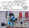
hello please help me with this FM transmitter ,i tried to make it work but it didn't so does any one know
that if this circuit works or not and if it doesn't why !
i am sure i didn't do anything wrong but maybe i did but any one can help me to ensure that the circuit works !
see the attachment.
NOTE :
L1 and L2 is equal to 10 turns of 1mm enameled wire close wound on a 3mm form.
this circuit from this site :
http://www.circuitdiagram.org
 

Attachments

  • long-range-fm-transmitter-circuit.gif
    long-range-fm-transmitter-circuit.gif
    9 KB · Views: 141
Such a high frequency circuit is very sensitive to layout. It should be done on a PCB. How is the circuit constructed?
 
I was going to say, it's kind of difficult to tell what you did wrong just by looking at the schematic :p:D 
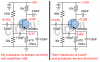
We really need to see your setup.

Also, as crutschow said, high frequency circuits shouldn't be built on a breadboard. They should be built on a PCB to avoid poor, intermittent connections. That alone may be your problem. Also, the position of the coils are very important. How close they are to each other and the rest of the components makes a huge difference. Long wires should be avoided, and the circuit should not be touched while in operation--the output frequency is very sensitive to the surrounding capacitance, which is changed when your hand is near. There are all sorts of things that could go wrong, so a PCB is definitely ideal.

Der Strom
 
My FM transmitter is almost the same except it has a preamp with pre-emphasis and a voltage regulator. It works very well.
 

Attachments

  • FM transmitter pic + schem.PNG
    FM transmitter pic + schem.PNG
    195.9 KB · Views: 148
In their MP3 FM Transmitter project the dumbos show my mic preamp with pre-emphasis circuit but with its 1.5V battery then it DOES NOT WORK!
 

Attachments

  • mic preamp with pre-emphasis.PNG
    mic preamp with pre-emphasis.PNG
    10.3 KB · Views: 114
Last edited:
thank you every one i will try audioguru circuit.
But it is the same circuit. Yours should work almost the same (except its frequency changes as the battery runs down, it doesn't have a mic preamp so its mic is not sensitive and it sounds muffled).
Did you use an electret mic?
How did you build it?
 
It won't matter what design you use if you don't pay attention to the things mentioned earlier. They most likely won't work on a breadboard, regardless of the schematic, and they are all very sensitive. Make sure you take this into account when building your circuit.

Der Strom
 
Status
Not open for further replies.

Latest threads

Back
Top