Continue to Site

Welcome to our site!

Electro Tech is an online community (with over 170,000 members) who enjoy talking about and building electronic circuits, projects and gadgets. To participate you need to register. Registration is free. Click here to register now.

  • Welcome to our site! Electro Tech is an online community (with over 170,000 members) who enjoy talking about and building electronic circuits, projects and gadgets. To participate you need to register. Registration is free. Click here to register now.

[help] home weather monitoring miniproject

Status
Not open for further replies.

alkoko111

New Member
Hi every body .

i'm working now on the home weather project using the LM35 temperature sensor.

The goal of my project is the take readings from the sensor and displaying it on the computer recipient through the parallel port, thus a program is provided here to display the readings,which is written by c#.net programming language.

achieving this issue , other components included to our circuit such operational amplifier LM358 and ADC0804 convertor.

My question here is : what is the benefit of the opreational ampilifer in our circuit ?

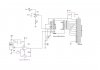
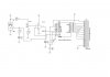
this is the circuit diagram of my project :
**broken link removed**
 
The output from some analogue sensors is not enough (or is in the wrong range) for an analogue input. Opamps can be used to invert a signal or shift it into a suitable range for the analogue to digital converter.

Looking at the configuration of the opamp, I think it might just be acting as a buffer. Someone with more experience will be able to correct me on this.
 
thnx

edeca ..... thank you for your help . if u get any new more information, this is will be helpful.

i have an other question here :
from the configuration of the circuit .... the pin9 ( Vref/2 ) and the pin20(Vcc or Vref) is related together , i mean the value of pin9 is taken according the value of the pin20 which mean, i MUST adjust the value of the pin9 by dividing the value of pin20 ..... for instance , if the value of Vcc is 5 so :

Vref=Vcc/2 = 5/2=2.5 volt .... this is the value that must be on pin9

from my searching i knew that value can be adjusted by adjusting the value of the variable resistance (RV1) ...... the question is :

Is that correct ? if it is not , how could that be ?

NOTE : check the attachment , i attached an other pic for the circuit with good resolution .

thank u
 

Attachments

  • acd0804&lpt.JPG
    acd0804&lpt.JPG
    45.2 KB · Views: 692
hi,
As the input to the LM358 does not have any type of pre-regulation, the LM358 is not required.
RV1 and R3 will do the same action, ie: give +2.5V to Vref

For greater accuracy and repeatability the Vref should be regulated.
Voltage references for 2.5v are not expensive.

The +2.5Vref sets the SPAN of the adc,, that means as the adc has 8 bit resolution, an LM35 input signal of 2.5V will give a adc value of 255 [FFh].
 
Here's a 2.5v reference I've used before with analogue temperature sensors. It requires only one capacitor (between Vout and GND) and costs almost nothing. It is in a tiny package too, making it ideal.

MCP1525

Eric, why was the LM358 included in the first place? Perhaps that part of the circuit was stolen from somewhere that wasn't using a uC input?
 
eric ....thank you for your information.

i need more explanation about the last part u wrote :
The +2.5Vref sets the SPAN of the adc,, that means as the adc has 8 bit resolution, an LM35 input signal of 2.5V will give a adc value of 255 [FFh].

* you mentioned the span of the ADC , which is determined by the formula :

RES=Vref/m
assuming m: the value of the 8-bit combination after converting into decimal

* you mentioned also, lm35 input signal will give the adc value of 255 [FFh] .

will the ADC 8-bit always has the value of 255. or the value depend on the formula I wrote ?
 
If you use an 8 bit ADC, you will always get a value in the range 0-255 (the size of an 8 bit register).

If you use a 2.5v reference, 0 will be 0v and 255 will be 2.5v. This is why sensors that "scale" to 2.5v and precision voltage references are so useful.

There are also 4.096v references, which work in an identical way for a 10 bit ADC.
 
eric ....
will the ADC 8-bit always has the value of 255. or the value depend on the formula I wrote ?

No the ADC will give a value proprtional to the voltage input from the LM35.

The LM35 in the way that you have it wired will only measure from +2C thru +150C deg.
As the LM35 output is not amplified in your circuit, the LM35 will output from +20mV at +2C thru to +1.5V at +150C

So the very maximum adc conversion [with a 2.5Vref] will be [1.5/2.5] *255 =153 decimal.
I would suggest that the LM358 is used as an amplifier for the LM35 output.

Do you follow OK.?:)
 
Last edited:
i need more explanation .... and thank you for your respond

hi,
Its difficult to know which part you require an explanation for,
if you ask a specific question/s, we can answer.:)

If you mean the formula: its [+V input to the ADC0804 divided by the Vref voltage] multiplied by the ADC0804 max bit resolution in decimal.
As its 8bit resolution, that a max numeric value of 255

So thats: [LM35/2.5] * 255

At:
2Cdeg[ +20mV],,,, [0.02/2.5]/255 = 2
20Cdeg[ +200mV],,,, [0.2/2.5]/255 = 20
100Cdeg[ +1V],,,, [1/2.5]/255 = 102
 
Last edited:
hi,
This is your original circuit, edited to show the LM358 as an amplifier for the LM35 output.

Set the gain of the LM358 to give the max output voltage that the ADC will accept. With a Vref of 2.5V that will be 2.5Vmax

Say your max temperature is going to be 50Cdeg, which is 0.5V outfrom the LM35, if you set the gain of the LM358 to *5, that will give a voltage input to the ADC of 2.5V at 50Cdeg.

By using the amplifier it will increase the temperature resolution of the circuit.

Effectively the LM35 will be now 50mV/degC, which is a ADC change of 5 counts,
that means a resolution of of about +/-0.2C per ADC bit.
 

Attachments

  • acd0804&lpt.JPG
    acd0804&lpt.JPG
    49.1 KB · Views: 733
Last edited:
hello guys ..... sorry i'm late for my reply.

-First of all , thank you all for u help eric and edica .

-By the way i have soldered my circuit on the first configuration and make test on it to check the functionality of it , and it seems working fine, and I implemented my program after connecting the circuit with the parallel port and it works fine.

-About the operational amplifier, on the first configuration it was not working as an amplifier as ERIC said. i search about that with my team and we figured out that, it is working as an insulator between the input voltage coming from the RV1 and the output voltage of the opamp to the pin9(Verf/2). The reason is to guarantee that the value RV1 is stable because sometimes, even the pin9 is an input pin and logically, it must not carry any value on it ( no voltage ), but practically , if u measure the value of it, you will notice that carries some voltage, so this value will included to that coming from RV1which mean, the results will be an expected . WHAT DO YOU THINK GUYS ? CORRECT ME IF I've MISTAKEN

-Finally, i want to talk about the Vref I applied , as follows :

Vref=1.28 v then we will apply Vref/2=0.64 v on the pin 9 .
according to the formula [LM35/Vref]*255

WHAT WILL BE THE TEMPERATURE ? as eric calculated on 2.5 v
 
-About the operational amplifier, on the first configuration it was not working as an amplifier as ERIC said. i search about that with my team and we figured out that, it is working as an insulator buffer
between the input voltage coming from the RV1 and the output voltage of the opamp to the pin9(Verf/2).
The reason is to guarantee that the value RV1 is stable it will not make Vref stable because sometimes, even the pin9 is an input pin and logically, it must not carry any value on it ( no voltage ) its Vref ,
but practically , if u measure the value of it, you will notice that carries some voltage, so this value will included to that coming from RV1which mean, the results will be an expected . Sorry, this part dosnt make any sense
WHAT DO YOU THINK GUYS ? CORRECT ME IF I've MISTAKEN

-Finally, i want to talk about the Vref I applied , as follows :

Vref=1.28 v then we will apply Vref/2=0.64 v on the pin 9 .
according to the formula [LM35/Vref]*255

WHAT WILL BE THE TEMPERATURE ? as eric calculated on 2.5 v

The adc value is [Vinp/Vref] * 255 .. Pin9 is the Vref pin and Pin6 is Vinp

If you set Vref at 1.28V and input 2.5V you will still get the max adc value output of 255.
BUT why would you want to do that.?
 
Now ...i have confused .

Firstly, about the LM35. it gives 10mV/Centigrade, is that correct ? if it not so what is it ?


secondly, how could I know the value of Vin ?

Finally, you told of why i would do that ? about the Vref= 0.64v . is this wrong because i choose this value ? really i don't know .....one of my friends suggested that ...... tell me your theory , eric .

hi,
There is nothing to get confused about.:)

The LM35 outputs 10mV/Cdeg change.
The way you have the LM35 wired on your original circuit enables the LM35 to work over the range of +2C thru +150C.
Thats a Vin [ to the adc] of +20mV thru +1.5V.

I suggested a Vref of +2.5V, this means that a Vin to the adc of +2.5V would give an adc value of 255.

As your project is for a limited temperature range, say +2C thru +50C, it would make sense to amplify the LM35 output so that a tempr of +50C would give a voltage Vin to the adc of +2.5V,,, which would give the max resolution from the adc of 255.

So I suggest you use the LM358 in your original circuit as an amplifier for the LM35.

OK.?:)

EDIT:
Please tell me what actual temperature range you require and I will post a LM358 amp circuit.
 
Last edited:
okey .... i understood .

As your project is for a limited temperature range, say +2C thru +50C, it would make sense to amplify the LM35 output so that a tempr of +50C would give a voltage Vin to the adc of +2.5V,,, which would give the max resolution from the adc of 255. i think u talked about this , but please would u clearify it again i mean how will amilfy it to give you 50 c for 2.5 v

The range between 2 to 60 degcent .... ok

i want to ask about the accuarcy of the a LM35 , from the datasheet it is a +0.5/-0.5 , knowing this value , in what that will help me ?

thank you
 
okey .... i understood .
The range between 2 to 60 degcent .... ok

i want to ask about the accuarcy of the a LM35 , from the datasheet it is a +0.5/-0.5 , knowing this value , in what that will help me ?

thank you

hi,
So your Tmax is 60Cdeg, the LM35 will output +0.6V for 60C.

If you set the LM358 to a gain of 4.17, this will increase the 0.6V to 2.5V.
So for Tmax the adc [with a Vref=2.5] will have an Vinp of 2.5V which will convert to 255 decimal.

In your PC program you will have to multiply the 255 by say,2.353 to make it equal to 600, which be equivalent to 60.0Cdeg

As an option, as you are amplifying the LM35 output to the ADC, you could just use the +V[5v] ref of the ADC.
This would mean amplifying the LM35 0.6V by 8.33, so the 0.6V would become 5V, which with a +5Vref would give 255.
This method for the Vref is simpler and cheaper.!

If you think about it, if you made the Tmax = 51Cdeg, so the LM35's 0.51V was multiplied by 9.8 to +5V, this would give an adc value of 255.
When multiplied by 2 in the PC program would give 51Cdeg.!

The +/-0.5C accuracy is over the temperature working range of the LM35.

OK.?
 
ok ..... allright .

???? i did not get it

thank you very much eric .

hi,
Look at this graph from the LM35 data.
Examine the Tempr plot over the full range of the LM35.
 

Attachments

  • AAAimage01.gif
    AAAimage01.gif
    29.2 KB · Views: 272
Status
Not open for further replies.

Latest threads

New Articles From Microcontroller Tips

Back
Top