Continue to Site

Welcome to our site!

Electro Tech is an online community (with over 170,000 members) who enjoy talking about and building electronic circuits, projects and gadgets. To participate you need to register. Registration is free. Click here to register now.

  • Welcome to our site! Electro Tech is an online community (with over 170,000 members) who enjoy talking about and building electronic circuits, projects and gadgets. To participate you need to register. Registration is free. Click here to register now.

HELP HELP HELP: not inverting OpAmp with variable gain

Status
Not open for further replies.

pagini

New Member
I'm looking for a smart solution to obtain a different gain for a not
inverting OpAmp The goal is have the same gain at the beginning and at the
end of the ramp source 0-5V DC signal (NO FREQUENCY) and a different gain in the middle of the ramp.

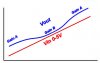
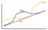
As example (where Vi= DC ramp signal, A=OpAmp gain)

Vi=1 A=2, Vi=2 A=1,5 Vi=3 A=1 Vi=4 A=1,5 Vi=5 A=2

In the attached img in red the source ramp, Vu1 and Vu2 the possible results
wanted

Thanks for any help
 

Attachments

  • Curva.jpg
    Curva.jpg
    11.5 KB · Views: 194
Last edited:
Do you realise you have "triple" posted!..


>> Vi=1 A=2, Vi=2 A=1,5 Vi=3 A=1 Vi=4 A=1,5 Vi=5 A=2

Do you want the Gain to change abruptly at these points or to change slowly as you have drawn?
 
Last edited:
Please don't make duplicate posts, they're very annoying and don't help you or us to help you. Creating duplicate threads does not increase your chance of a useful response, it only reduces it as people get confused and can't always see what others have suggest in the other thread.

Why do you want to do this?

What exactly are you trying to do?

The chances are you're doing it the wrong way.
 
Last edited:
Hello Pagini, and welcome to the forum.

I've had a bit of a think about this and personally I can't see any way to achieve your goal with simple op-amp circuits alone. For me, there would have to be some form of decision making going on which is more the realm of DSPs.

I'll be interested to hear other people's suggestions?

By the way, I think you accidentally posted three times. Ooops!

Brian
 
Hang on a second though, what if you were to run this signal through a voltage to frequency converter circuit first? Then feed it into an op-amp setup as a filter with low-end and high-end cut offs.

Just a thought.

Brian
 
hi brian,

If he wants abrupt Gain transitions I was thinking along the lines of using a dual comparator window detector
that would run in 'parallel' to the main amp.

If the comp window was setup at the transition voltages it could switch in resistors on the input of the main amp,
using FET's..

He may want a gradual change in Gain, he hasnt replied.

Regards
 
Eric,

Yes that is a bit of a grey area. The graph seems to show a gradual transition though so I'm tending to sway towards that for the moment. You do have a good idea though and it may well prove to be far simpler than mine. I always think the KISS way is best (Keep It Simple, Stupid).

I was thinking of using a colpitts oscillator with varicaps which would alter the output frequency in response to a change in voltage. The output of the oscillator could then be fed into an Op-Amp filter with cut off points set where he wants the gain to fall off.

Brian
 
Last edited:
First of all sorry for my double (or more) posted, but I have had something like a crash of my browser. Absolutely without any intention to increase chance of useful response!
Sorry also for my pore English!
Even though I do not have good experience on OpAmps, I know quite well comparators. It should seems a good idea make a voltage "window trap" to recognize the ramp zone where to change the gain, but I need a gradual transition though, as Eirc understood.
Because the source ramp changes very slowly and it cycles in a not repettive way, I think is not possible to use a band pass filter or something like this.
I perfectly know that the solution (if does exist) probable is not possible with only one OpAmp, but I wolud avoid to solve it with very complex circuit or with a microPIC
Thanks again for any suggestion
Sorry again for my terrible English
 
Pagini,

Your English is not that bad, I am able to make sense of what you are saying. However, I would advise you to fill in the location information within your profile as this helps others understand that you may print some occasional spelling mistakes or confused words.

With regard to your problem, it seems to me that the VCO to Filter solution is the way to go. I have considered your suggestion that the slow ramp and non-repetative properties of the signal would have an ill-effect on the solution, but I don't feel this is the case.
The VCO will effectively give you an output frequency range which is in direct proportion to the input voltage. Therefore, as your signal ramps up or down so the frequency output will change up and down.
Then, you feed this signal into a filter based around a non-inverting op-amp with cut off points on the lower and higher end of the frequency range. These cut off points would be chosen to reflect where you want the transitions to occur and is probably best acheived by experiment.

With the information you have provided so far, I feel this is your best option. Again, I would be interested to hear more solutions from the others on the forum.

If you can give us the bigger picture with regard to the project itself, it may help us think of a solution which better fits your problem.

Brian
 
ThermalRunaway said:
Irrelevant in this particular example as sufficient explanation of the problem was given (all be it some minor details unclear)
It is relevant.

It's highly likely that there is a far better way of doing what he wants.

All too often people approach things from completely the wrong direction. Then (after further intergeneration and 50 odd replies) they tell us exactly what the circuit for so we point them in the right direction and something that appeared quite complected turns out to be pretty simple.

Read his post!
I did, if he worded it properly then maybe I might understand what exactly.

If he told us exactly why he wants to do this then we could point him in the right direction.

Such a negative response. He didn't actually offer any of his own suggestions, so I'm not sure where you get that from. But he painted the basics of the problem quite clearly from where I'm sitting.
How was my response negative?

The only negitive comment my post contained was a reprimand for posting the same thread three sodding times so he bloodywell deserved the negative comment!
 
Hero999

I think everyone would agree that more information is always helpful. My point is there was enough information there to provide a positive response. He even provided a graphical description of the basic problem. His wording is slightly off key due to English being a second (or third or fourth) language, but personally I'm not having a problem understanding it.

Regarding the repetative posts, we have a new forum member here as can be clearly seen from his post count (this was his first thread). Newbies are entitled to make mistakes, I think you'll agree, and he has already explained that a browser crash caused the multiple posts.

I don't think a "reprimand" is required at all. Positive contribution, that's what is required.

Brian
 
Oh I didn't notice his reply!

pagini said:
I wolud avoid to solve it with very complex circuit or with a microPIC
Do you mean you don't want to use a PIC?

Surely wouldn't that be the best solution though?

The only other thing I can think of that would be able to give such an odd response is an op-amp with the feedback resistors connected via analoge switchs which are connected to some comparators which would be horrible.
 
hi Pagini,

Are we 'hitting the can'?

Need more input!
 
This thread is all over the place. How's about using a VGA (variable gain amplifier) and feed the gain control (Vg) a triangle waveform. So you get same gain at endpoints and a different gain at midpoint.
 
That's a nice idea. I guess you could do that using an Integrator. His variable voltage would be the input to the Integrator, and he would obtain your triangle waveform at the output which could be used to feed the variable gain input of the Amp.

Brian
 
Eric, you are right for the location: done!
The solution that I’m looking for regards an improvement for some controls in the train plastic of a friend of mine.
The Vin = 0-5V comes from a position sensor ( I think a potentiometer).
Eric, your suggestion is a VCO + band pass filter, …correct?
Optikon, may you explain better your proposal?

Thanks to all of you……something of good is coming out!

PS
I added a new img reviewed (I hope more clear than the previous)
 

Attachments

  • Curve1.jpg
    Curve1.jpg
    22.4 KB · Views: 171
Pagini,

I think it would be useful for you to experiment with both of the ideas. Optikon's seems a little simpler than the VCO+filter idea, but personally I'd investigate both and then choose one based on circuit performance. Neither of them should be particularly hard to design.

Brian
 
Thinking about it though, if your input signal (0-5V) is always a slow ramp signal like you've drawn in your picture, then you won't need the triangle wave generator at all. Just some signal conditioning on the original signal and use that to alter the gain of the VGA.

Brian
 
pagini said:
Eric, you are right for the location: done!
The solution that I’m looking for regards an improvement for some controls in the train plastic of a friend of mine.
The Vin = 0-5V comes from a position sensor ( I think a potentiometer).
Eric, your suggestion is a VCO + band pass filter, …correct?
Optikon, may you explain better your proposal?

Thanks to all of you……something of good is coming out!

PS
I added a new img reviewed (I hope more clear than the previous)

Hi pagini,
This was Brian's suggestion, not mine, but I would go along with the idea.
 
Status
Not open for further replies.

Latest threads

New Articles From Microcontroller Tips

Back
Top