Continue to Site

Welcome to our site!

Electro Tech is an online community (with over 170,000 members) who enjoy talking about and building electronic circuits, projects and gadgets. To participate you need to register. Registration is free. Click here to register now.

  • Welcome to our site! Electro Tech is an online community (with over 170,000 members) who enjoy talking about and building electronic circuits, projects and gadgets. To participate you need to register. Registration is free. Click here to register now.

Help Controlling 7-seg with Arduino

Status
Not open for further replies.

jcan

New Member
It's my day off work so I had some time to mess around with my little Arduino. I salvaged a 4-digit display off of an old microwave and I'm trying to get the arduino to control one of the digits. I started with the basic "blink" code and messed around with it a bit. I was able to get the display segments to light up by setting the digital pins to OUTPUT and turning one on at a time...but I can only get two segments to light up before things start getting too dim. I haven't had a chance to use the arduino in more then 4 months...so I've lost most of what I've learned in the past.

Here's the code I have:
-------------------------------------------

//int led = 1;


void setup() {
pinMode(0, OUTPUT);
pinMode(1, OUTPUT);
// pinMode(2, OUTPUT);
// pinMode(3, OUTPUT);
// pinMode(4, OUTPUT);
// pinMode(5, OUTPUT);
// pinMode(6, OUTPUT);
}

void loop() {
digitalWrite(0, HIGH);
delay(1);
digitalWrite(0, LOW);
digitalWrite(1, HIGH);
delay(1);
digitalWrite(1, LOW);
}
-------------------------------------------

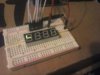
That code lights up two of the segments, as shown in the photo.
 

Attachments

  • CAM00218.jpg
    CAM00218.jpg
    294.2 KB · Views: 366
I learned quite a bit from this page:
http://allaboutee.com/2011/07/09/arduino-4-digit-7-segment-display-tutorial/

Specifically how a simplified way to toggle the digital pins.
I wired up the pins similar to how the tutorial describes, except I only have one of the digits active right now until i can find a couple more resistors. I eliminated pin 8. So far so good, I have the first (far right) digit counting down from 9 to 0 each second

New code: (this snippet just displays "3" on the first digit, but you should get the general idea)
----------------------------------------------
// 1 = PORTD=B11001111;
// 2 = PORTD=B11001110;
// 3 = PORTD=B10000110;


int d1=9,d2=10,d3=11,d4=12;
int tick=5;

void setup()
{
DDRD=0xff; // all pins 0-7 OUTPUTs
DDRB=0xff; // all pins 8-13 OUTPUTs even though we only use pins 8-12
PORTD=0x00; // make pins 0-7 LOWs
PORTB=0x00; // make pins 8-13 LOWs
}

void loop()
{

digitalWrite(d2,LOW);
digitalWrite(d3,LOW);
digitalWrite(d4,LOW);
digitalWrite(d1,HIGH);
PORTD=B10111111;delay(tick);
PORTD=B11011111;delay(tick);
PORTD=B11101111;delay(tick);
PORTD=B11110111;delay(tick);
PORTD=B11111110;
// digitalWrite(8,HIGH);
delay(tick);

}
----------------------------------------------
 
this might help understanding here too

A register generally holds a word
Called one byte or 2 nibbles or 8 bits
Like 11111111 or 11011001
These values tell the chip what to do
By shifting the bits right or left you change the word and consequently what the chip does
Its pretty complex and you can do it to any register I think. As in your case you can assign the port a binary value too
To understand what your post is doing you must look to the register and see how it is set before the action and how it is set after the action
In some registers for instance changing a 0 to 1 turns on a port (say an LED attached).
 
hi
First you should learn to use digital multimeter to confirm segments and bits,Generally speaking, there are at least four digital tube has 12 pins, eight segments and four bits. Use a multimeter can simply go to confirm their position.Secondly, if you want to control it, you need to light up eight LED. Through different combinations, to display numbers.
Thanks
 
I might be totally off here but I'll take a stab at it. I didn't review all the code so that could be an issue, but the problem might be electrical. I don't know about these segments but maybe they draw so much current that they load-down the power supply. You might need a separate power supply and drivers to get enough power to the LEDs.

I mention that because you stated they were getting "dim" if you light more than two. Of course that could also be because your software, if it individually scans the LEDs and only leaves them on for a short period, the percentage of on time vs. off time may be too small to allow the LED to consume enough power even if the power supply is good.

You may not realize it but most LEDs can be turned on for about 4X their rated current as long as they are only on for 10-25 % of the time, so a change to the driving voltage or current-limiting resistors could solve this. The only gotcha is that if you have a software issue and leave one single segment or digit on when the software stops/crashes, you could overheat those LEDs.

So maybe I'm off base but what the heck, it was at least worth mentioning.
 
Status
Not open for further replies.

Latest threads

New Articles From Microcontroller Tips

Back
Top