Continue to Site

Welcome to our site!

Electro Tech is an online community (with over 170,000 members) who enjoy talking about and building electronic circuits, projects and gadgets. To participate you need to register. Registration is free. Click here to register now.

  • Welcome to our site! Electro Tech is an online community (with over 170,000 members) who enjoy talking about and building electronic circuits, projects and gadgets. To participate you need to register. Registration is free. Click here to register now.

HELP!Automatic Temperature Controller

Status
Not open for further replies.

Spark.Shi

New Member
Dear all

**broken link removed**

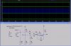
This is what i do an automatic temp control circuit,it can work but sometime the relay will beating a few times(fast),and then return normal.

So where can I do to improve it!

Thanks of all

Spark.Shi
2010.12.10
 

Attachments

  • 2010-12-10_112417.png
    2010-12-10_112417.png
    21.7 KB · Views: 117
Last edited:
How is it built/wired? (PCB, Strip-board,Plug-board?)

You likely have a ground loop where the relay current (which flows into the ground path out of the emitter of the switching transistor) produces a voltage drop across some part of the wiring between the opamp and the thermistor.
 
Last edited:
From just a quick glance at your schematic, it appears your comparator has no hysteresis and may be false triggering from either some noise on the input or some other fluxuation of the input signal. I'll do a quick sim and get back to you.
 
Doesn't R7 produce hysteresis?
 
Mike and Spark,

Unless I've drawn it wrong somewhere, I don't believe the comparator is set up to function at all as expected. I ran the sim and stepped the inverting input at 7 levels from 4.5V to 7.5V and got 4 different output states. I've attached the sim.

I have been over it several time looking for drawing errors, but can't find any. The symptom described could be from the changing resistance of the sensor in conjunction with the configuration.

I forgot to note the input Vs. output levels:

4.5V in = 12V out
5.0V in = 4.1V out
5.5V in = 8.75V out
6-7.5V = 0V out
 

Attachments

  • Bad Comparator.jpg
    Bad Comparator.jpg
    158.7 KB · Views: 119
Last edited:
Status
Not open for further replies.

Latest threads

Back
Top