Continue to Site

Welcome to our site!

Electro Tech is an online community (with over 170,000 members) who enjoy talking about and building electronic circuits, projects and gadgets. To participate you need to register. Registration is free. Click here to register now.

  • Welcome to our site! Electro Tech is an online community (with over 170,000 members) who enjoy talking about and building electronic circuits, projects and gadgets. To participate you need to register. Registration is free. Click here to register now.

HEF4030B (Quad XOR) How to connect? Pls. help :(

Status
Not open for further replies.

edlim

New Member
Hi all,

I'm a newbie in electronics... so i really need your help.
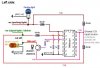
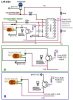
Now from the pics attached prob. should be clear on my desired ooutput.

What i want to do is, when i ON my car parking light, it will then ON also my signal (fender) light. But when i activate my signal lights (blinks), the signal will alternate the fender light ON / OFF and when i deactivate the signal, it will remain ON (provided my parking light is still ON).

I'm not sure whether can this work? Also, what's the purpose of;
1. Vdd
2. Vss
on the chip?
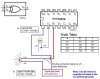
I tried to have it power via an adaptor but it seems that it shows the signal out of pin#3 voltage even if pin#1 and pin#2 has signal of 6Vdc. However, the output shows 3Vdc on pin#3. The -ve i connect directly to -ve terminal of my multimeter while the +ve to pin #1 and loop to pin #2 for testing. Pin#3 is connected to +ve terminal on the multimeter.
When i short the 6Vdc on pin#1 and pin#2, output on pin#3 still shows a power of 3Vdc.

Pls. help.

Thanks a million.

Rgds.
Edwin.
 

Attachments

  • mywiring.jpg
    mywiring.jpg
    36.1 KB · Views: 809
which is positive? and which is ground?
i also tested this way...

same test perform on the 6 vdc adaptor, but with the +ve i loop to Vdd and -ve loop to Vss, well kinda weird. I powered Pin#1 with 6V but Pin#3 shows me a 0v. Then i powered pin#2 with 6v but pin#3 still reads 0v. Finally pin#1 and pin#2 with 6vdc but pin#3 still reads 0vdc

Now am confuse.
Oh ya, can i directly connect my +ve from my car light to the chip and not blowing it. Coz this chip input is 3v - 15v but Amp / Watt i dunno.
Also, will the output be the same as my input volt / watt. Do i need something to increase volt / watt?

thanks checkmate :)
 
Most IC chips need to be powered. For this chip, Vdd needs to be connected to the +ve rail of your power source, and Vss needs to be connected to the -ve rail of your power source.

As for voltage requirements, refer to **broken link removed** and download the HEF Family Specifications. It's stated there, Vdd = -0.5V to 18V. Vi = -0.5V to (Vdd+0.5)V. Max current in/out is 10mA.

If your input is 12V and your Vdd is 6V, just halve your 12V with a simple potential divider.

As for current requirements, 10mA output will never power your parking light. You can simply use ohm's law to estimate that the light requires 40+mA of current. You will need to use the output to control a transistor that will be used to switch on/off a high current rail for your fender light.

Lastly, I do not quite understand how you connect your parking light to I2.
 
hi again...

yup. i have downloaded the file.
but dun really understand though :(

here's a more clear idea of what i would like to achieve.
Also, can u help me in sketching out draft for me.
Pic 1, parking light not ON (1), hence signal as normal.
Pic 2, parking light ON, signal active blinking, but when rear and front light active (3) and (4), fender light (2) does not lid.
Pic 3, parking light ON (1), fender also ON (2), but blinking inactive for rear and front (3) and (4).
Pic 4, parking light ON (1) and fender light ON (2) but signal switch not activated / not turn on.

Also, do I need to replace something at A, B, C, D, E. If yes, do you know the component code.

Thanks a million bro.

Cheers.
 

Attachments

  • 4030.jpg
    4030.jpg
    60.3 KB · Views: 734
First of all, 40 series IC's are CMOS, they have a very high input resistance. This can be a problem with your inputs. does your signal processor output a clean 12V (logic 1) and 0V (logic 0)? or does it leave the inputs floating at one point? in the second case you need to add a resistor to keep the input pulled-up or down, depending on the situation

The same applies to input I2, but the lamp will probably act as a pull down resistor.

Then, like checkmate already told, the outputs of the chip can only sink or source a couple mA's, certainly not enough to light a lamp. You'll need to buffer the output with a transistor.

there's also a possibility that your 'signal processor' can't handle enough current to power the 2 lamps connected to it and it might require a buffer too. Again, no way to tell from here .
 
hi checkmate,

if possible, my input and also the Vdd i would like to share 12Vdc (easier as there's no other avail power source).


hi Exo,
i guess my input would be a steady 12v input as it's origin from the car's parking light and the signal light. However, the watt for the parking light i guess it's 10-15watt while the signal (fender) is about 5-10watt. I'm gonna connect direct from the source of the parking light and signal light (+ve) to the I1 and I2 terminal of 4030.

For the output... there's only a bulb (12v at 5-10watt).

Based on my wiring diagram, is the components used okie / match.
Coz i'm gonna have them stuck on a board... with connectors.

Also, regarding the transistor, it produce 600mA (frm the datasheet) but it is sufficient to power my bulb (also what watt will it be and it's voltage) as I'm looking for at least 12V with at least 5watt. Say my input to it would be at 12V between 5-15watt, is the output from the transistor same?

Should i use 2N2907 or 2N2907A. Any recommendation on transistor that would produce 12V at 5watt min. and input 12V at max 15watt.

Also... regarding the resistor, which watt applies here... 1/2 watt, 1 watt , 5 watt?

Sorry about so many question...
i'm an absolute dummies in component as i'm not EE stud.
I like to hands on experiment and to DIY most things...
it just gives me the pleasure.


P/s: The power supply to the chip... i have no choice but to share with either any activated bulb (parking light / signal) as there's the only 12V i get. Else, for a direct 12V (+ve) from the car battery might definitely screw up the chip (burned).


Thanks a million guys.
I really need this help.

Cheers. :D
 

Attachments

  • 4030-conn.jpg
    4030-conn.jpg
    30.7 KB · Views: 607
oh ya...
the design was derived from this forum too...
it was a diagram to something similar...
except it was design for brakes and signal bulb with the similar truth table.
i changed / drop some resistor as i assume it might not be needing it..
i maybe wrong ...

cheers.

p/s: thanks to them for initiating my DIY.
 
some of the diodes on your drawing are facing the wrong way... The only diode facing the right way is the bottom right one, all others should be the other way around.

edlim said:
Also, regarding the transistor, it produce 600mA (frm the datasheet) but it is sufficient to power my bulb (also what watt will it be and it's voltage) as I'm looking for at least 12V with at least 5watt. Say my input to it would be at 12V between 5-15watt, is the output from the transistor same?
It's a bit more complicated, there aren't any 'watts' going into and coming out of a transistor, only current. Watts are the product of current going through a device and the voltage drop over that device...

As you need to power a 5watt lamp @ 12V you first need to calculate how much current it requires.
Current (in Ampéres) = Power (in watts) / Voltage (in... volts :lol: )
5W / 12V = 416mA, so yes, this transistor would be able to do it...

But you do have another problem with this scematic, by using this transistor (a PNP) this way, it switches the lamp on when the chips output is 0V. So you're inverting your logic (the lamp will be on when it needs to be off and vice versa)...
The way you should do this is by getting a NPN transistor (a 2N2222 is the NPN complement of your 2N2907). Connecting its emitter to ground, it's base to the chips output trough a resistor , and put the lamp between +VE and the collector...

edlim said:
Also... regarding the resistor, which watt applies here... 1/2 watt, 1 watt , 5 watt?
I assume you mean the transistors base resistor...
A normal 1/4 watt resistor would do
 
Dear Exo,

Sorry for late reply.
Was kinda tied up with work lately :(

Here's my new sketch... but the connection on the NPN transistor...
I am a little confuse. I ask help frm the electronic shop.. gee... hopeless.
They know nuts :cry:
Do let me know, which is right, A / B. If both wrong, care to sketch for me, using point 1,2,3 and my pics (Ms. Paint for the sketch).

Also.... 2N2222 is already obsolete... can you recomend anything similar..
I browse the net, but there's no similar or i not sure how to find it on semiconductors.philips.com

Thanks a million. I purchase the resistor 1K and 3.3K and diode i think its N4001 as they claim should work.

Cheers.

P/s: Thinking of working on it this weekend.

Thanks... great help frm ya :lol:
 

Attachments

  • 4030-conn1.jpg
    4030-conn1.jpg
    59.8 KB · Views: 663
Hi Exo,

I found a transistor... which might be the same...
It's 2N3904, do you think it works same as 2N2222

Thanks. :)
 
Let me make your requirements clearer in a truth table. Hope I got it right, as your explaination is really confusing.

P - Parking Lights
S - Signal Lights
F - Fender Lights

P S | F
---------
0 0 | 0
0 1 | 0
1 0 | 1
1 1 | 0

Hmm ... doesn't look like an XOR operation. By boolean algebra notation,

F = and(P, not S)
= not(nand(P, not S))
= nand(nand(P, nand(S, 1)), 1)

Seems like a quad NAND gate would do the job.
 

Attachments

  • logic_192.jpg
    logic_192.jpg
    21.9 KB · Views: 524
You need to connect the transistor as in picture B...
A 2N3904 won't do it, it can only handle 100mA

BC337, BC368,...ig you can get them
 
hi checkmate,

err, actually.... the truth-table for XOR is correct.
Let me amke it clearer...
P = parking light (with bulb).
F0 = Original Fender light (with bulb) which is also a signal indicator below your car side door mirror.

New requirements. Totally disconnect F0 from it's bulb.
Hence i will be getting only the signal (contact) but no more the bulb.
Now the bulb will then be replaced with new connection +ve and gnd (-ve).

P F0|F1
--------
0 0 | 0
1 0 | 1
0 1 | 1
1 1 | 0

In my scenario, i didn't insert a new bulb. I'm using the existing bulb but new signal into it (+ve and -ve).
Now i tap the +ve of the parking light to I1,
next take the disconnected original fender light +ve to I2.
The output on O1 will be connected directly to bulb +ve and -ve (gnd).

Cheers.
 
Hi Guys,
I would like to add my two cents (or sense) of input.
A little transistor is rated to drive a cold LED, not a cold incandescent light bulb. A light bulb's current rating is when its filiament is at thousands of degrees, and the current is about 10 times greater when it is cold. So a little 2N3904 or BC337 will have more than 4 Amps through it, and be expected to dissipate more than 12 Watts for a moment. Poof!
Use a PNP power transistor (for the original circuit), rated at 6A like a TIP42, and a little 2N3906 inverter driving it. Then it will be reliable.

Don't forget to ground unused inputs on the gate IC.
 
dear Exo,

pic B is correct then....
can i conclude that on the transistor...
the emitting (#1) will be triggered when signal is received on (#2)
Since the blub is currently parellel with the +ve taken from tapped wire on Vdd link (either frm Paking or Signal)... it WILL NOT LID the bulb unless it's triggered on #2 from the CMOS 4030.
Generally, the emitting side actually connects / link #3 to #1 if received signal frm #2 (on O1 of 4030) similarly like a NC/NO relay.

So when my parking light is ON, it will trigger 4030, send signal to the transistor and have my fender light ON as well. Trigger on I1.

"Truth table 1"
P F | F
-------
1 0 | 1

In the day-time when my parking light OFF, it will act normally as a signal light (fender). Trigger on I2.

"Truth table 2"
P F | F
-------
0 1 | 1

When my parking light ON (triggering "Truth table 1") and my signal light triggered, it will then goto "Truth table 3" which will OFF the bulb (fender light) and when the signal blinks OFF the bulb be activated. It will interloop between Truth table 1 and Truth Table 3 which in other words, will have the signal lights on the fender working opposite signal whenever a signal is triggered.

"Truth table 3"
P F | F
-------
1 1 | 0

Scenario... LEFT side.

When PARKING bulb OFF. Strike a SIGNAL... blinking
1. Front bulb - ON/OFF
2. Rear bulb - ON/OFF
3. Fender bulb - ON/OFF
- all as its blinking at an internal...

When PARKING bulb ON. Strike a SIGNAL... blinking
1. Front bulb = ON/OFF
2. Rear bulb = ON/OFF
3. Fender bulb = OFF/ON
- fender as in blinking opposite signal with the front and rear bulb.

I hope my explanation is clear -checkmate.
And Exo, can i achieve this without delay of opposite blinking signal / fender lights. Coz the used of a relay there's a certain delay but the used of CMOS delay is much lesser (milli secs.) as i was told.

Thanks bro Exo.
Hope i can find such transistor....
 
edlim said:
And Exo, can i achieve this without delay of opposite blinking signal / fender lights. Coz the used of a relay there's a certain delay but the used of CMOS delay is much lesser (milli secs.) as i was told.

It's pretty much instantanious...
 
Status
Not open for further replies.

Latest threads

New Articles From Microcontroller Tips

Back
Top