Continue to Site

Welcome to our site!

Electro Tech is an online community (with over 170,000 members) who enjoy talking about and building electronic circuits, projects and gadgets. To participate you need to register. Registration is free. Click here to register now.

  • Welcome to our site! Electro Tech is an online community (with over 170,000 members) who enjoy talking about and building electronic circuits, projects and gadgets. To participate you need to register. Registration is free. Click here to register now.

Heathkit oscilloscope help

Status
Not open for further replies.

rojaul

New Member
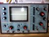
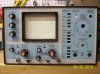
I recently inherited a Heathkit 35 MHz Dual Trace Oscilloscope Model IO-4235. It has not been used in aprox 15 years. it was in proper working order the last time it was used.

The unit turns on and I am able to obtain a trace with the panel controls set to the operation manual's preset specifications. I adjusted the Horizontal position and centered the trace right-to-left with no problems. The focus and intensity also adjusted without issue.

The only thing that I can not seem to adjust is the Y1 or Y2 vertical position. turning either knob produces no change on the CRT.

also, I am not able to get any type of wavelength to produce on this unit.


I have let the unit warm up for about 30 mins, no change.
I have visually inspected the circuit boards, nothing looks damaged


any suggestions on what to check next?
 

Attachments

  • oscope.jpg
    oscope.jpg
    62.4 KB · Views: 708
As best I can tell from the photo (it is rather blurred), the input coupling switches are set to GND, thus shorting out the inputs.
Set them to AC or DC as required, and it will probably work OK.

JimB
 
Thank you for your reply. Yes, I have tried that, still the same. My problem is that I can not even adjust the vertical (up/down) placement of the trace on the crt when trying to set up the device initially.

sorry for the blurred picture, it was taken from my cell phone, I will try to take a better one tonight with the camera in video mode.
 
OK, upon further investigation I have found a 6µF non-polar Capacitor that seems to be leaking. this was located on the " A Time Base Board". It has some white crusty stuff near one end. not sure if this would cause the problem I have, but I will change it anyway.
I also took another picture of the front panel, much clearer this time, but half of the knobs were removed in order for me to remove that capacitor.

any other suggestions?
 

Attachments

  • cap.JPG
    cap.JPG
    1.1 MB · Views: 665
  • oscope1.JPG
    oscope1.JPG
    1.2 MB · Views: 959
The problem is probably in the vertical (Y) deflection output stage. Open output transistors, dead power supply in that section, or could be as simple as a broken wire lead from the vert output to the CRT. Careful, deflection voltages are not insignificant!
 
Has to be the vertical amplifiers, vertical output stage, or the power supplies that feed them. In my heath scope, I recall there were +100V and -100V power supplies to run the vertical stage power output. There were lower voltage supplies to feed the signal amplifier stages. Power supplies often fail, and Heathkit equipment was notorious for weak power supplies.
 
Last edited:
Usually, after a careful inspection of the circuitry, you would want to verify that all power supply voltages are within spec.

In something that old, you should probably either test the ESR (Equivalent Series Resistance) of every electrolytic capacitor or replace them. If you don't have an ESR meter, but do have a scope and a square/pulse generator (or a 555 timer circuit), you can try the method at **broken link removed** . It does work pretty well, even for in-circuit caps.

If it's not something easy like an electrolytic, you should get the service manual.

It's been quite a while since I've worked on scopes, so this might not be quite right, but here goes: The deflection circuits are often a sort-of "balanced" two-sided affair, with two identical-looking sets of components, which helps in diagnosing them. When a vetical position knob is turned away from the center position, the voltages in the two parts of the deflection circuits will change from equal to not equal, moving away from equal in opposite directions from each other, by about the same voltage difference. Then, where you find that is not happening, you are near the problem. You should be able to follow the wires or traces from the vertical position pots to find the related circuitry.

If BOTH channels are not working, that should be a huge clue and should narrow it down considerably. (And might just point to a hopefully-simpler power supply problem, as someone already mentioned.)

Good luck,

Tom
 
Last edited:
Status
Not open for further replies.

Latest threads

New Articles From Microcontroller Tips

Back
Top