Continue to Site

Welcome to our site!

Electro Tech is an online community (with over 170,000 members) who enjoy talking about and building electronic circuits, projects and gadgets. To participate you need to register. Registration is free. Click here to register now.

  • Welcome to our site! Electro Tech is an online community (with over 170,000 members) who enjoy talking about and building electronic circuits, projects and gadgets. To participate you need to register. Registration is free. Click here to register now.

Heathkit IP-27 Power Supply Trouble

Status
Not open for further replies.

EN0

Member
--------------------------------------------------------------------------------

Hey Fellows,

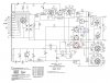
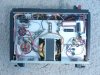
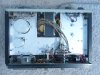
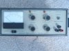
I'm fixing up an old Heathkit IP-27 power supply for a friend because it isn't working properly. At first It wasn't working at all, but when I took out the fuse and put it back in, it started working again (but not to its full potential). So It was a little dirty and needed some cleaning. Apparently, when you have a load you shouldn't get any voltage drop and the power supply will compensate for the loss voltage. So the voltage stays the same no matter the load. Unfortunately, this isn't happening and when I put a 100Ω resistor around 5V or so the voltage dropped significantly. My first guess is replacing the electrolytic caps since those don't last very long; but I might be wrong. How can I fix this? Here is the schematic because I couldn't find the whole manual online:

https://www.nostalgickitscentral.com/...chema_ip27.gif

I'd appreciate the help!
 

Attachments

  • HeathkitIp-27PowerSupply 001.jpg
    HeathkitIp-27PowerSupply 001.jpg
    139.7 KB · Views: 811
  • HeathkitIp-27PowerSupply 002.jpg
    HeathkitIp-27PowerSupply 002.jpg
    146.3 KB · Views: 662
  • HeathkitIp-27PowerSupply 003.jpg
    HeathkitIp-27PowerSupply 003.jpg
    161.3 KB · Views: 678
no schematic on that link...........
 
What a beautiful old supply!! With a 70v neon voltage regulator valve too!

Many of those rotary switches carry the entire PSU output current and high resistance contacts on them could be the cause of your symptoms.

After testing/replacing caps you should clean all the pots and rotary contacts with spray cleaner. You can also test the rotary switches with a good ohmeter across the switch contacts since there seems to be room to get in with the multimeter probes.

Voltages are marked on the schematic so you can check the voltages.

Probably just replacing some caps and cleaning/working all the pots and switches should get it up and running.
 
Thanks for the correct link and the suggestions. I'm not sure that the caps are bad but they might be. Is there a way to test them? I suppose that if they aren't good, the capacitance rating wouldn't abide to the correct value? So, the voltage drops but it isn't supposed to but the current should, correct? Just making sure...;)

I noticed that when I had a higher current, the voltage didn't drop as much. Could something be attenuating the current? I guess I should clean everything first and then I'll see what I should do next.

Thanks for the help!
 
A discrete design like that could have just about anything blown in it. The elect caps probably are funky. may still be functional at reduced performance.

Ditto on the comment that the contacts in all those rotary switches could be oxidized and flaky.
 
Last edited:
Right, I'll go ahead and replace the caps for maximum performance and also clean the contacts.

Standby! I'll let you know how it works after that.
 
Ok, I cleaned the contacts and polished the outside (to make it look nice and clean...;) ) and now the analog meter doesn't seem to work. It remains at the same level even when I adjust the output voltage!
 
I agree with the previous poster in that the rotary switch on the front carries all the current. Put the output under load, measure the voltage across the first smooting cap, C2, 3000uF and see if the voltage drops. Then it is probably dirt on the switch. If the ripple is excessive (you really need a scope for this) then chances are the cap has degraded.

I would then move towards the output and see where things start to misbehave:D
 
... looking at the first, leftmost, image that was posted.
Does the black capacitor, white stripe, look normal? Is the right endcap of this capacitor convex in shape? .... Is there any sign of swelling, or discoloration?

Can't tell from the picture .... would appreciate a clarification.

Electrolytic capacitors seem to be statistically prevalent as the primary mode of failure on aging or older electronic assemblies.
 
Ok, I'm getting about 4mV of DC ripple on that bulky filtering cap at the bottom left-hand corner on the first picture. Is this ok? What would be a good value?

For that capacitor with the white band, all of them are like that. They seem to be painted on one side. They are rated 1000uF at 50V.

Do you guys see that grey wirewound resistor by the bulky filtering cap? Well that's supposed to be 2.5KΩ but it is actually 3KΩ. I'm thinking of replacing that.

The meter doesn't work, it still says 10V with 5V output. The calibration is kind of funny too, when I spin that screw at the bottom of the meter it goes to zero where it should be, then if I keep going It will go up and then go back to zero.

Thanks for the help!
 
Check the voltages, they are marked on the schematic in the little ovals. Start closest to the transformer, then work through tht evoltages towards the output.

And first i would check the voltage on the neon and the main zener Z1 which derives the reference voltages for the supply regulation.
 
Ok, I checked to make sure I was getting the Vbe drop and the transistor at the far right corner in the first pic seemed to be fried. The one above was measuring a 0.4V drop and the bad one below measured 12V! Does anyone know where I can find a substitute transistor in addition to the datasheets for this sucker? I'd appreciate it!
 
I already told you. ;) It is an R256A transistor in the second picture. The two transistors you seen are shaped in the way of a bolt and both are the same transistor type.
 
I already told you. ;) It is an R256A transistor
No where in any of your previous posts above do you state that number or any other manufacturer's number.

But, here is how you second source a transistor:

1) Enter the PN in the search engine and start looking for it's data sheet or electrical specs.

2) once you know the key specs of voltage rating, collector current rating, gain and case style you go to transistor makers like motorola and shop for a power transistor similar to it.

If you can't identify the number, you estimate the needed specs based on surrounding circuitry, load current, etc.

BTW: on the schematic, there is an actual part number listed under the part labeled R265A device which is: 2N1309

I can't find any transistor on the schematic labeled R256A, which is the number you list above.

EDIT TO ADD: the 2N1309 is a germanium power transistor. I don't even know if germanium transistors are still available?

https://pdf1.alldatasheet.com/datasheet-pdf/view/120680/ETC/2N1309.html
 
Last edited:
No where in any of your previous posts above do you state that number or any other manufacturer's number.

But, here is how you second source a transistor:

1) Enter the PN in the search engine and start looking for it's data sheet or electrical specs.

2) once you know the key specs of voltage rating, collector current rating, gain and case style you go to transistor makers like motorola and shop for a power transistor similar to it.

If you can't identify the number, you estimate the needed specs based on surrounding circuitry, load current, etc.

BTW: on the schematic, there is an actual part number listed under the part labeled R265A device which is: 2N1309

I can't find any transistor on the schematic labeled R256A, which is the number you list above.

EDIT TO ADD: the 2N1309 is a germanium power transistor. I don't even know if germanium transistors are still available?

2N1309 pdf, 2N1309 description, 2N1309 datasheets, 2N1309 view ::: ALLDATASHEET :::

Sorry Bountyhunter, I thought I mentioned it. I post on two electronic forums so that explains why I thought that. Please accept my apologies! As for the transistor, it is gernamium. I tried looking up the datasheet, but I couldn't find it.
 
You didn't measure the transistor correctly. A Vbe tester (multimeter etc) won't return a Vbe reading of 12v.

How did you go measuring the voltages on the powered-up PSU and comparing them to the voltages clearly marked on the datasheet (as i said in a previous post)?
 
I found the bad transistor, it is circled in red. I substituted a PNP power transistor for it and it worked fine, except that it's a silicon transistor and I need a gernamium one. Does anyone know of a substitute for it?
 

Attachments

  • IP-27FraudTransistor.JPG
    IP-27FraudTransistor.JPG
    404.8 KB · Views: 1,139
I found the bad transistor, it is circled in red. I substituted a PNP power transistor for it and it worked fine, except that it's a silicon transistor and I need a gernamium one. Does anyone know of a substitute for it?
The transistor you circiled in red is wired in parallel with the one just above it in schematic. Those MUST be the same type of transistor or you will have serious problems because one will hog current and cook itself under load. Whatever transistor you installed in the red circle, put one in the above location as well.
 
Status
Not open for further replies.

Latest threads

New Articles From Microcontroller Tips

Back
Top