Matienzo
Member
Hi there,
I'm trying to create an electric heater for an insect repellent mat.

The only constraint is that I must use a 18650 battery.
The mats are about 35x50 mm and they need to be heated at about 130F.
In the chat, Mike_2545 suggested a power resistor like this one
and also pointed out these foot warmers
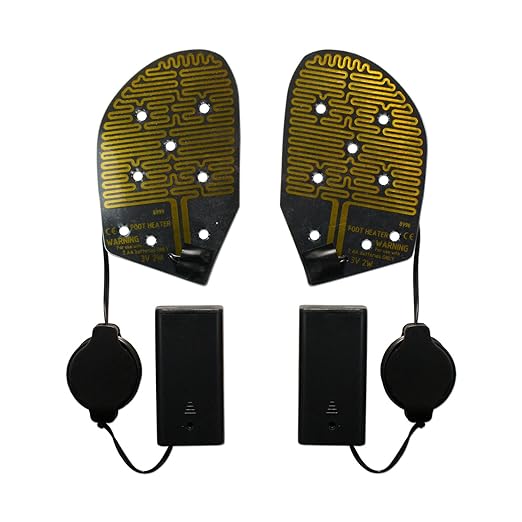
What approach do you think will give me more operation time? How would you go about making a resistance like the ones on the foot warmer?
Thank you for any guidance. I'll be closely following this thread today and tomorrow and I'll try to answer ASAP to any question.
Paulo
I'm trying to create an electric heater for an insect repellent mat.
The only constraint is that I must use a 18650 battery.
The mats are about 35x50 mm and they need to be heated at about 130F.
In the chat, Mike_2545 suggested a power resistor like this one
and also pointed out these foot warmers
What approach do you think will give me more operation time? How would you go about making a resistance like the ones on the foot warmer?
Thank you for any guidance. I'll be closely following this thread today and tomorrow and I'll try to answer ASAP to any question.
Paulo

")

