Continue to Site

Welcome to our site!

Electro Tech is an online community (with over 170,000 members) who enjoy talking about and building electronic circuits, projects and gadgets. To participate you need to register. Registration is free. Click here to register now.

  • Welcome to our site! Electro Tech is an online community (with over 170,000 members) who enjoy talking about and building electronic circuits, projects and gadgets. To participate you need to register. Registration is free. Click here to register now.

HeadPhone Summing amp.

Status
Not open for further replies.

MikeMl

Well-Known Member
Most Helpful Member
I need an IC for a mono amplifier:

Primary input power: 14Vdc with alternator ripple, typical automotive (i.e. needs good PSRR).

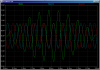
Output: 6Vp-p into 35Ω load.

Gain: 1 (unity, inverting ok).

Two switched inputs: (need isolation between inputs, i.e. "summing amp", level on input A not effected by input B being switched on-off, and vice-versa).

Input impedance: ≥ 500Ω, single ended, ground referenced.

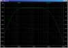
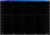
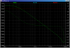
Frequency Response: flat between 100 to 5000Hz with 6db per octave roll-off above and below.


It seems a standard opamp cannot drive a 35Ω load. I'm thinking LM386N1? Other suggestions??
 
Last edited:
Here is what I came up with:

headphoneamp-png.51831


First Plot is Time Domain response with 1000Hz and 1111Hz inputs, and with 2Vp-p of simulated alternator ripple on the 14V input.

Second Plot is the frequency response with a single input, showing unity gain

Third Plot is the frequency response with both inputs, showing gain of 2, sum of the the two inputs.

Fourth Plot is the Power Supply Rejection Ratio from the 14V input port to the Output.

Fifth Plot is the FFT of the time domain response, showing low intermod between the inputs and good suppression of the alternator ripple.
 

Attachments

  • HeadPhoneAmp.png
    HeadPhoneAmp.png
    29.6 KB · Views: 490
  • HeadPhoneTimeDomain.png
    HeadPhoneTimeDomain.png
    30.9 KB · Views: 181
  • HeadPhoneSingleInput.png
    HeadPhoneSingleInput.png
    28.3 KB · Views: 175
  • HeadPhoneBothInputs.png
    HeadPhoneBothInputs.png
    28.6 KB · Views: 179
  • HeadPHonePSRR.png
    HeadPHonePSRR.png
    29.5 KB · Views: 175
  • HeadPhoneFFT.png
    HeadPhoneFFT.png
    30.1 KB · Views: 180
Last edited:
Status
Not open for further replies.

Latest threads

New Articles From Microcontroller Tips

Back
Top