MrDEB
Well-Known Member
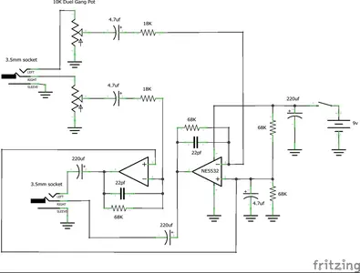
I ordered a kit from Amazon
Hopefully this will work as desired
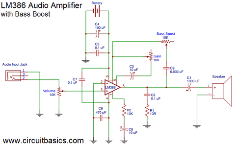
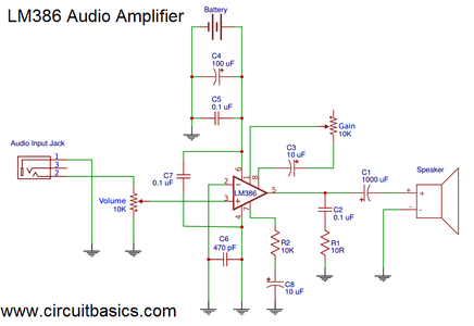
or see attached file with LM386
Amazon.com: Velleman, Inc – Super Stereo Ear MiniKit MK136 – Entry Level Audio Amplifier Soldering Project : Electronics
Amazon.com: Velleman, Inc – Super Stereo Ear MiniKit MK136 – Entry Level Audio Amplifier Soldering Project : Electronics
www.amazon.com
or see attached file with LM386