diy didi
Member
Hi All.
I’m busy building the final output opamp buffer stage for my mono headphone amp.
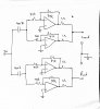
I have managed to build the output stage using opamps configured as non inverting buffers and using 1ohm current sharing resistors to effectively parallel the two sections of a dual opamp.
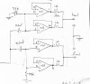
I however only realized afterwards that I need to use an inverting buffer topology as my preceding mixer/ gain stage is inverting also.
This will give me absolute phase from input socket to output socket.
What are the drawbacks of using the inverting topology over the non inverting topology? If any.
I can see that the parts count is higher and that I would have to increase the input coupling cap value.
I have attached the two circuits. Sorry for the jpegs.
Thanks in advance.
I’m busy building the final output opamp buffer stage for my mono headphone amp.
I have managed to build the output stage using opamps configured as non inverting buffers and using 1ohm current sharing resistors to effectively parallel the two sections of a dual opamp.
I however only realized afterwards that I need to use an inverting buffer topology as my preceding mixer/ gain stage is inverting also.
This will give me absolute phase from input socket to output socket.
What are the drawbacks of using the inverting topology over the non inverting topology? If any.
I can see that the parts count is higher and that I would have to increase the input coupling cap value.
I have attached the two circuits. Sorry for the jpegs.
Thanks in advance.