Triode
Well-Known Member
I'm trying to make this lcd useful. I've found plenty of example that just hand you the C18 code, such as this
and **broken link removed**
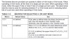
Im currently trying to do the second one (code at bottom so it doesn't cloud up the post). The code compiles, but I'm confused about the connections. It specifies the connections to the LCD as:
My question is, isn't it a problem to use PORTB for two things? pins B4,5 and 6 are being used for specific things, then again for the whole set of data lines. I figured it might mean to skip them, but then there arent enough, data lines to the LCD are 7-14, (datasheet for my lcd) which requires all of a port. If I use them all, well the chip doesn't detect to program, so I don't know that the LCD wouldn't work. Which I guess might just mean I have to connect it all with some overlapping but not connect the programmer and the LCD at the same time, but that doesn't make sense to me anyway, because how could you use the same pin for two things?
Maybe I just need to redefine the outputs, but I haven't worked with serial communication much, so I'm not sure how to do that, I don't even see in this code where they define which outputs to use.
little help?
Edit: after posting this I found this guide and I'm going through it, it looks pretty through, I'll post if it works in case someone else comes in here looking for how to do this.
and **broken link removed**
Im currently trying to do the second one (code at bottom so it doesn't cloud up the post). The code compiles, but I'm confused about the connections. It specifies the connections to the LCD as:
PORTBbits.RB4 Pin used for the E line.
PORTBbits.RB5 Pin used for the RS line.
PORTBbits.RB6 Pin used for the RW line.
Data Lines PORTB
My question is, isn't it a problem to use PORTB for two things? pins B4,5 and 6 are being used for specific things, then again for the whole set of data lines. I figured it might mean to skip them, but then there arent enough, data lines to the LCD are 7-14, (datasheet for my lcd) which requires all of a port. If I use them all, well the chip doesn't detect to program, so I don't know that the LCD wouldn't work. Which I guess might just mean I have to connect it all with some overlapping but not connect the programmer and the LCD at the same time, but that doesn't make sense to me anyway, because how could you use the same pin for two things?
Maybe I just need to redefine the outputs, but I haven't worked with serial communication much, so I'm not sure how to do that, I don't even see in this code where they define which outputs to use.
little help?
Edit: after posting this I found this guide and I'm going through it, it looks pretty through, I'll post if it works in case someone else comes in here looking for how to do this.
Last edited: