Continue to Site

Welcome to our site!

Electro Tech is an online community (with over 170,000 members) who enjoy talking about and building electronic circuits, projects and gadgets. To participate you need to register. Registration is free. Click here to register now.

  • Welcome to our site! Electro Tech is an online community (with over 170,000 members) who enjoy talking about and building electronic circuits, projects and gadgets. To participate you need to register. Registration is free. Click here to register now.

Having Trouble with H-bridge

Status
Not open for further replies.

Cry_Wolf

New Member
Hello Every Body,

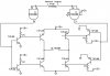
I want to drive a 10A motor with h-bridge. A friend of mine suggested me a simple design(given below)

After making the PCB, when i plugged in power supply, The PNP Transistors went ****** hot. Can any body explain whats the problem? Where am i wrong?

Any help and suggestions will be appreciated.
 

Attachments

  • hbridge.JPG
    hbridge.JPG
    47.1 KB · Views: 215
You should put current limit resistors on the bases of your PNP devices. Something like 120 ohm.
 
In addition to the base resistors on the PNP transistors, you should put base resistors on the TIP122 transistors (total 4 places), perhaps 4k7 ohm (4.7k).
 
Thanks i got it working by adding 1k resistors to the base of every transistor.


Its working very fine..;)


Any suggestions and/or corrections?????
 
If you don't need 10A then it should be good the way it is.

If you really need 10A you'll want to decrease the resistors in the bases of the TIP147s and TIP42s. (Another 1K in parallel, or Mikebits suggestion of 120 ohm 1W is good). You'll also want to change the pull up resistors on the lower TIP drivers.

Do not change the other 1K resistors.
 
The original circuit had the micro-controller driving the dead short of the base of the TIP122 darlington transistors, and the TIP122 darlington transistors driving the dead short of the base of the TIP147 darlington transistors.

The circuit was a smoke generator.
 
The circuit was a smoke generator.

What was the duration of smoke generation? This might be handy for laser light show projects :)
 
I think the duration of the smoke was only long enough to make it POP.
 
The circuit was a smoke generator

OP said they got very hot.. no mention of smoke. Perhaps the supply was current limited.

Unfortunately there was no smoke and i end up burning my fingers:D.

And thanks mneary and Mikebits for your suggestion of the resistor values. It will help me a lot.

Edit:
And Yes, Fortunately the supply was limited (1A Adapter):D

Regards
 
Last edited:
Hi Cry Wolf, can you post your Dia. with the revisions. I'm trying to make the same circuit. DC motor only 6 amp with added e-brake, controlled by PWM 30 amp.
Thanks in advance
 
Status
Not open for further replies.

Latest threads

New Articles From Microcontroller Tips

Back
Top