Hey guys, I am having a bit of trouble getting USART to work. I am using two PIC18F4550 and two XBEE wireless modules for commication between PICs. I believe I have the XBEE set up correctly and would like to make sure that I have both of the microcontorller's code properly written before I proceed to troubleshoot further. I am using MPLAB v8.8 with C18 LITE. Additionally, I am using Microchips library for hardware USART (packaged with C18) as shown below.
Here are the code snipets for both the transmitting and receiving microcontroller:
Transmitting Microcontroller:
Receiving Microcontroller:
I have both microcontrollers oscillating at 8MHz. I have calculated the Buard rate to 9600 using the second formula:
SPBRG = (Fosc/(64 x Baud rate)) - 1, BRGH=0
SPBRG = (8MHz/(64 x 9600)) - 1 => 12.02, so I used 12
And, from the code above, I believe both microcontrollers are set to work using asynchronous communication
My question are as follows:
1. Is it okay to have the openUART() function within the main while loop
2. Do I need the closeUART() function when I am done reading?
3. Is there something I am missing that I am not configuring?
Any additional information or foresight as to what I may be doing wrong is much appreciated. Thank you.
Here are the code snipets for both the transmitting and receiving microcontroller:
Transmitting Microcontroller:
Code:
#include <p18f4550.h> // Uses Microchip's predefined library for 18F4550
#include <delays.h>	  // Uses Microchip's predefined library for delay methods
#include <usart.h>    // Uses Microchip's predefined library for hardware USART
...
		while(1)
		{
                 ...

                 // --Setup/initialize USART using predefined functions from Microchip's hardware USART library
			OpenUSART(
			      USART_TX_INT_OFF &   			 // disables transmission interrupt
			      USART_RX_INT_OFF &  			 // disables reception interrupt
    		              USART_ASYNCH_MODE & 			 // sets USART to asynchronous mode
    		              USART_EIGHT_BIT& 				 // sets USART to use 8-bit data mode
    		              USART_CONT_RX &  				 // sets the port in continues receive mode
    		              USART_BRGH_LOW,  				 // uses the low speed Baud rate formula
			       12					// sets Baud to 9600 BPS using 8MHz in calculation (actual baud rate is 9600.614)
     		              );

			while (BusyUSART()); // Makes sure the serial port isn’t busy
	                sendUARTbyte1=(char)(tempReadIn1&0xFF00);	// Get MSB byte for sensor T1
			sendUARTbyte2=(char)(tempReadIn1&0x00FF);	// Get LSB byte for sensor T1
			WriteUSART(sendUARTbyte1);			// Send MSB byte for sensor T1
			WriteUSART(sendUARTbyte2);			// Send LSB byte for sensor T1

			sendUARTbyte1=tempReadIn1&0xFF00;	// Get MSB byte for sensor T2
			sendUARTbyte2=tempReadIn1&0x00FF;	// Get LSB byte for sensor T2
			WriteUSART(sendUARTbyte1);			// Send MSB byte for sensor T2
			WriteUSART(sendUARTbyte2);			// Send LSB byte for sensor T2

			CloseUSART();

...
}
Receiving Microcontroller:
Code:
#include <p18f4550.h> // Uses Microchip's predefined library for 18F4550
#include <delays.h> // Uses Microchip's predefined library for delay methods
#include <usart.h> // Uses Microchip's predefined library for hardware USART
...
while(1)
{
...
// --Setup/initialize USART using predefined functions from Microchip's hardware USART library
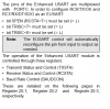
OpenUSART(
USART_TX_INT_OFF & // disables transmission interrupt
USART_RX_INT_OFF & // disables reception interrupt
USART_ASYNCH_MODE & // sets USART to asynchronous mode
USART_EIGHT_BIT& // sets USART to use 8-bit data mode
USART_CONT_RX & // sets the port in continues receive mode
USART_BRGH_LOW, // uses the low speed Baud rate formula
12 // sets Baud to 9600 BPS using 8MHz in calculation (actual baud rate is 9600.614)
);
while (BusyUSART()); // Makes sure the serial port isn’t busy
readUARTbyte1=ReadUSART(); // Get MSB (byte) for sensor T1
readUARTbyte2=ReadUSART(); // Get LSB (byte) for sensor T1
tempReadIn1 = readUARTbyte1; // Set MSB (byte) for sensor T1
tempReadIn1 = tempReadIn1 << 8; // Shift byte
tempReadIn1 += readUARTbyte2; // Set LSB (byte) for sensor T1
readUARTbyte1=ReadUSART(); // Get MSB (byte) for sensor T2
readUARTbyte2=ReadUSART(); // Get LSB (byte) for sensor T2
tempReadIn2 = readUARTbyte1; // Set MSB (byte) for sensor T2
tempReadIn2 = tempReadIn2 << 8; // Shift byte
tempReadIn2 += readUARTbyte2; // Set LSB (byte) for sensor T2
CloseUSART();
tempReadTotal1 = tempReadIn1;
tempReadTotal2 = tempReadIn2;
...
}I have both microcontrollers oscillating at 8MHz. I have calculated the Buard rate to 9600 using the second formula:
SPBRG = (Fosc/(64 x Baud rate)) - 1, BRGH=0
SPBRG = (8MHz/(64 x 9600)) - 1 => 12.02, so I used 12
And, from the code above, I believe both microcontrollers are set to work using asynchronous communication
My question are as follows:
1. Is it okay to have the openUART() function within the main while loop
2. Do I need the closeUART() function when I am done reading?
3. Is there something I am missing that I am not configuring?
Any additional information or foresight as to what I may be doing wrong is much appreciated. Thank you.
Last edited: