engineergc
New Member
Hi,
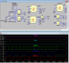
My purpose is in this circuit is obtain 3 outputs as motor rotation direction(cw and ccw) and motor rotation. Motor rotation output gives 5 volt when motor turn otherwise it gives 0V output.Motor rotation output doesn't depend on motor rotation direction. By using CD4013B I wil obtain CW and CCW signals. But at the output I expect at least 50 ms pulses therefore I used LTC6993 entegres to obtain 50 ms outputs.
In this design hall3 output is my reference.By using CD4013B flip flops system determines hall sensor orders.If order is hall1,hall2,hall3 bldc motor turns to CW. When order of hall sensors is hall1,hall3 and hall2 motor turn to ccw. Also system has 3 main outputs.These are cw,ccw and rotation outputs.When motor turns rotation output gives 5V,otherwise it gives 0V. If motor turns to CW, CW output is 5V and ccw output is 0V.When motor turns to ccw, ccw output is 5v and cw output is 0V. This BLDC motor phasing is 120 degree.
My problem is; I can not obtain cw and ccw outputs correctly. When motor turns to CW outputs is 0V and CCW is 5V. And also I changed motor rotation direction after 200ms. But I can not obtain correct waveforms at the outputs of CW,CCW and rotation. Could you help me what are the wrong things in my design?
")
