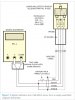
I have an automotive 3 wire Hall Effect Sensor for a speedo from a Ford Falcon-I want to use it in a kit car speedo application, but I am unable to identify the function of each of the wires.
Is there a simple test I can do to identify which is Ground, 12v power and signal . I am concious that I cant just experiment with 12v , as I run the risk of blowing it.
Hoping someone can help
Patrick
Is there a simple test I can do to identify which is Ground, 12v power and signal . I am concious that I cant just experiment with 12v , as I run the risk of blowing it.
Hoping someone can help
Patrick