Continue to Site

Welcome to our site!

Electro Tech is an online community (with over 170,000 members) who enjoy talking about and building electronic circuits, projects and gadgets. To participate you need to register. Registration is free. Click here to register now.

  • Welcome to our site! Electro Tech is an online community (with over 170,000 members) who enjoy talking about and building electronic circuits, projects and gadgets. To participate you need to register. Registration is free. Click here to register now.

Hall effect magnetmeter

Status
Not open for further replies.

levangram

New Member
Hi everybody!
I have a llittle problem...I'm relatively new to these projects,so i would appreciate any help!
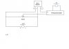
What i'm trying to do is to build a simple magnetometer with a hall effect sensor.I use a digital panel meter and i want it to show me not the voltage output of the sensor,but the present magnetc field's flux density.The equation is B=(V-2.5)/2.5
So that for example if the voltage output that i count is 2.5,my indication to be 0.if my voltage is 5,the indicator to display 1 and so on.
How exactly can i converty my voltage in this way?
I know that i have to use an opamp with 2 resistors with a ratio of 0.4 to invert (V-2.5) so that it's divided with 2.5.What i didn't know is how to invert my voltage to Vout-2.5.
Sorry if my questions are stupid...:(:(
 
Take a look at my thread on doing math with instrumentation opamps.

In my thread, I was trying to implement out=1.8 * in +32 for DegC to DegF conversion. The amplifier actually realizes the equation 1.8 (in + 32/1.8) [a little algebra there]. I ended up with a gain of 1.8, and a voltage on the In- pin of -177mV.

Your situation is more straight forward as your equation out= (v-2.5)/2.5 directly converts to out=0.4 * (in -2.5). Therefore, connect the hall effect output to in+, apply 2.5V to In-, and set the gain to 0.4. Done.
 
Thanx a lot!I managed to zero adjust my indication,but i have a problem with the op amp,as i've never used one before!
I know i have to connect 2 resistors with a ratio of 0.4 to the - input of the opamp and between the - and the out of the op amp.But i don't know how to manage my voltage.
-First of all,does a simple 741 op amp that i have,needs to be supplied?And if so,with what voltage?
-Second.I have the 2 leads,the hall sensor output and the wiper af a pot.where exactly of the 8 legs of the op amp do i connect them to?Do all 8 have to be used?
Sorry if my questions are stupid,i've never used an opamp before....
Anyone?:confused::(:confused::(
 
Thanx a lot!I managed to zero adjust my indication,but i have a problem with the op amp,as i've never used one before!
I know i have to connect 2 resistors with a ratio of 0.4 to the - input of the opamp and between the - and the out of the op amp.But i don't know how to manage my voltage.
-First of all,does a simple 741 op amp that i have,needs to be supplied?And if so,with what voltage?
-Second.I have the 2 leads,the hall sensor output and the wiper af a pot.where exactly of the 8 legs of the op amp do i connect them to?Do all 8 have to be used?
Sorry if my questions are stupid,i've never used an opamp before....

Why the pot? What is it intended for?
 
Someone else will have to chime in with the wiring for the 741, it's been too long since I've used a regular run-of-the-mill op amp.

The pot will go from power to ground with the wiper on 741 in-.
I'm not sure what to make of the 2 wires from the hall output. If there were three wires, the you have power and ground (self explanatory) and output which will connect to 741 in+. What's the 4th wire for?

Power and ground for the 741 will take care of 4 of the 8 pins. The there's the resistor network to set the gain, which I don't recall the wiring for, but does involve Vout. There's 5. what are the other 3 pins on the 741 that we're missing?

No,the hall sensor has 3 wires.One is for Vs(all ok),one is the common(all ok) and one is for the output.i connect the output of the sensor and the wiper of a pot to my indicator,and adjusting the pot,i actually zero my field.
What i'm trying now is to use the omp amp so that my new output will be 0.4 of the original(original comes from the output of the sensor and the wiper of the pot).I have a 741,but i dont know which wire goes where!!
a)which wire goes to op amp -?
b)which wire goes to op amp +?
c)does an op amp needs to be supllied to work?And if so,with what voltage?
 
I need a schematic of what you have. I can't follow it. I think you need a second pot or resistor network to provide the 2.5 volt offset to In-. What ever wire is going to your "indicator" also goes to In+.

Yes, the 741 needs juice. V+ will need to be higher than the highest output of the sensor and low supply (ground or negative supply) lower than your lowest expected sensor output. The 741 is not rail-to-rail so you head and foot room, probably 1 to 1 1/2 volts higher and lower than the sensor range.
 
This is my schematic.at your right is the digital panel meter.Adjusting the pot,gives me zero voltage at zero magnetic field.if i leave it this way,it will show me the voltage difference under the presence of a magnetic field.so i need to multiply it with 0.4 before getting into the panel meter..
 

Attachments

  • untitled.JPG
    untitled.JPG
    15.6 KB · Views: 172
You don't need an op amp. Just another pot. Any multiplier less than 1 is a reduction accomplished by a resistor divider. Connect a 10K pot from the output to ground with the wiper connected to the panel meter. Set the pot for a 6:4 ratio.
 
I think you're right,that's ok for me for the time being...
It's just that an a later stage maybe i will have to add some other scales besides kG and i will have to use an amplifier anyway..
But you've helped me for the time being,thanks!!:)
 
Status
Not open for further replies.

Latest threads

New Articles From Microcontroller Tips

Back
Top