Good day everyone,
I've been trying to repair VFD from Rockwell / Allen Bradley - Powerflex 750 series - model number 22C-D045A103 - series A. Initially, we were having troubles with Fault 13 (Ground Fault) being displayed at random. After extensive troubleshooting we've managed to narrow it down to one of built-in current sensors being faulty.
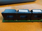
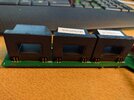
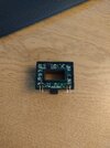
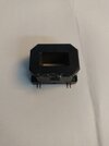
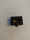
Unfortunately, the sensor itself does not have any marking printed. I've tried to open one up, but internal marking was not much better -at least I could not identify the component. I tried to look through DigiKey website in attempt to recognize the shape/appearance - again, none was matching.
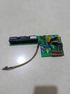
I managed to find an identical/similar board on AliExpress, but my worry is that it could suffer the same issue as our ones. What I've learned from Internet this fault was pretty comon back some time, so the chance are high. So I would like to try and source the components for the repair rather than relying on luck to get 100% working used board.
Below, I've attached some pictures of the component and current sensing board assembly. Have anyone come across such a critter? Any suggestions or leads will be greatly appreciated
Thanks in advance

