Continue to Site

Welcome to our site!

Electro Tech is an online community (with over 170,000 members) who enjoy talking about and building electronic circuits, projects and gadgets. To participate you need to register. Registration is free. Click here to register now.

  • Welcome to our site! Electro Tech is an online community (with over 170,000 members) who enjoy talking about and building electronic circuits, projects and gadgets. To participate you need to register. Registration is free. Click here to register now.

H Bridge Mosfet Fet P channel burned help!

Status
Not open for further replies.

roeebloch

New Member
Hi,
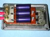
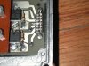
I have designed H bridge driven by Power Mosfet.
N ch - IRF2907
P ch IRF4905
The board get PWM from controller.
This board is connected to Motor type: NPC-T64 (very powerfull motor).
Some how P ch Mosfet always burns out, I don't have any idea why this happenes.
Attached schematic.
And datasheet of componnents.
The voltage to Motor is 36V.

Does any one had this problem before?

Thanks,
Roee.
 

Attachments

  • Mosfet V2.pdf
    22.5 KB · Views: 905
  • IRF4905.pdf
    110.3 KB · Views: 531
  • IRFP2907S.pdf
    115.9 KB · Views: 362
  • dynamometer_NPC-T64.gif
    dynamometer_NPC-T64.gif
    6 KB · Views: 628
Hi,
I don't know about your specific problem as I have used H-bridge designed in a different way (4x N-channel MOSFET and HIP 4082) but there are a few things in general you should check, for example:

1. Vgs - check that when you open the MOSFET you don't exceed the max. Vgs
2. shoot-through - when both N and P MOSFETs are open on the same side (even momentarily) it is like a short circuit - how do you control your H-bridge ? some controllers (like the mentioned Intersil HIP4082) insert a small delay when switching the MOSFETs to give the first one time to get completely closed before opening the second one
3. emf - motor is an inductive load and if both MOSFETs are turned off there can be voltage spikes which can exceed the maximum Vds for your MOSFET.

Petr
 
The motor starts and stalls with a current of 110A but the puny little P-channel Mosfet blows up with a current that is more than "only" 74A.
 
Mosfets

Hi,
If you will look again at the schematic diagram - you will see that there are 3 Mosfets of 74A (conected in parralel for each channel) - and the total is 226A.
Thanks,
Roee.
 
Last edited:
Your schematic has only two P-channel Mosfets in the H-bridge, not six.

Three Mosfets in parallel have a very high gate capacitance that the 1k and 2k resistors charge and discharge very slowly. Then the Mosfets spend most of the time as a very hot linear amplifier instead of switching quickly. That is why Mosfet driver ICs have an output current of Amps.

Your N-channel Mosfets are turned on from 300 ohms which is also pretty high then are turned off with 10 ohms which is good. It is much better than the 1k and 2k used for the p-channel Mosfets.
 
What sort of heat sink are you using. Note the derating with temperature and the temperature rise per watt.

John
 
Schematic

Hi Again,
The schematic is made using Orcad.
That means if the net has the same name it is consider connected.
So if you will look at top right and top left - you will see aditional 2 fets at each of the sides.

About timing you are correct, it depends also about PWM frequency, and my frequency is a little problematic in this case (14Khz), charge is about 5 Thao, wich is 5*R*c, that gives me maximum freqeuncy of 6Khz, otherwise Mosfet as you said will work on linear mode, and not saturation.

I Also considering to work only with N-chanel H bridge, with DC to DC that will make higher than 36V in order to turn on The NMOSFET that is connected to 36V, did any one try this before?

Is any one has any circuit that can drive out about 150A ??
Thanks for your help,
Roee.
 
Last edited:
Is any one has any circuit that can drive out about 150A ??
Thanks for your help,
Roee.

I have built two using basically the same design. One runs an old Ford 6V starter motor at 12V ("long-shaft" starter, used now in tractors) and a 12V treadmill motor that was rated at 1.5 to 2 HP. The basic design used a TPIC2101 to create PWM, soft-start, and allow logic-level control. A bank of paralleled mosfets (each with its own gate resistor) was driven by an LT1158. I had a main capacitor as suggested by 4QD in its site. I used IRF3025, IRF1010E, and IRF1607 mosfets with either 4 or 5 for each leg. It was only a 1/2 H controller as there was no need to reverse. I don't know what the current was, but the Ford starter could actually be stalled briefly and not pop the mosfets.

I would be happy to share the schematic, but 1) it doesn't show the mosfets, as that part of the design was done in a CAD program; and 2) there is some logic and detection circuitry that is not relevant. Just follow the datasheet for the LT1158.

Here are some pictures.

John
 

Attachments

  • Power board 1reduced.jpg
    Power board 1reduced.jpg
    51.6 KB · Views: 767
  • Power board 2.jpg
    Power board 2.jpg
    373 KB · Views: 811
Last edited:
Hi Again,
The schematic is made using Orcad.
That means if the net has the same name it is consider connected.
So if you will look at top right and top left - you will see aditional 2 fets at each of the sides.
Orcad is stupid!
The "extra" Mosfets are not connected to anything.
 
It would be interesting to obtain an oscilloscope picture of the voltage at the p-channel FET gate node.... for several of your operating frequencies.
A slow rise and fall of the trigger waveform could confirm the problem.
... One reference stated that the gate turn on time should be less than 1 µSec... to avoid thermal run-away problems.
Maybe you could devise a way to modify the gate drive circuit .... so that it did not operate within the critical region of the Vgs vs. gate charge graph... fig. 6 on the IRF4905 data sheet.
You might have to consider how much the scope capacitance itself loaded the circuit...still, it might provide some useful diagnostic information.

... some relevant information may be found here ... in issue #223:
Circuit Cellar - The Magazine for Computer Applications
see:
Power Switching in the Real World (Part 2)
 
You might have to consider how much the scope capacitance itself loaded the circuit...still, it might provide some useful diagnostic information.
The 'scope has an input capacitance of about only 10pF.
But the Mosfets have an input capacitance of thousands of pF.
 
You need a push-pull driver for power MOSFETS (and a low value gate resistor) because of gate excursion. Blew up a lot of transistors before I learned.
 
Only two of your P-Ch MOSFETs are connected to "power36V"!!! The "extra" P-Ch MOSFETs are connected together to a node named "power12V" which does not appear anywhere else. So only one P-Ch MOSFET is in the circuit on each leg.
 
Status
Not open for further replies.

Latest threads

Back
Top