Continue to Site

Welcome to our site!

Electro Tech is an online community (with over 170,000 members) who enjoy talking about and building electronic circuits, projects and gadgets. To participate you need to register. Registration is free. Click here to register now.

  • Welcome to our site! Electro Tech is an online community (with over 170,000 members) who enjoy talking about and building electronic circuits, projects and gadgets. To participate you need to register. Registration is free. Click here to register now.

H-Bridge design

Status
Not open for further replies.

cartoonwally

New Member
Hey guys,
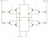
I've seen a few of the H-bridges designed by members of the forum lerking around but i wanted to see whether you thought that this one would work. I am driving the input with 4.8->6V from a servo (where the motor on the servo usually connects) and the ground from the servo circuit runs to the bottom of there. The thing i'd like to know is whether you think this circuit, and the circuit components ive chosen will work.

Q1,Q2,Q7,Q9 TIP2955 60V 15A PNP Transistor
https://www.electro-tech-online.com/custompdfs/2008/02/TIP2955.pdf

Q3,Q4,Q5,Q6 BC547 50V 100mA NPN Transistor
https://www.electro-tech-online.com/custompdfs/2008/02/BC547.pdf

R1->R4 1k0 resistor

Circuit is attached :)
Btw i am aware of some of the bugs i.e floating inputs...

Also, are those diodes imperative to the design? what do they actually do? and do i really need them? (this may be a really stupid qn, flame suit on)
 

Attachments

  • servo.JPG
    servo.JPG
    32.2 KB · Views: 1,721
Yes, those diodes are imperative. ESPECIALLY if you use BJTs (since MOSFETs have a parasitic diode in them that goes the same way, except that it is too slow to be of good use for this applicaiton but it can work in a pinch and at least gives something "to give"). A BJT doesnt have this parasitic diode and will therefore be the thing that gives first thus dying.

I don't feel like explaining it too much since I've had to do it a thousand times. BUt basically when you cut current flowing through an inductor (ie. the motor) the inductor tries to keep the current flowing (so called flyback current). If the current doesn't flow, then the voltage across the inductor will rise UNTIL the current does flow (the so called flyback voltage spike). With the diodes, they will turn on and the current will flow. Without them the votlage will keep rising until something gives to allow the current to flow (ie. the transistors will fry and become short-circuited). You want very fast, low forward voltage drop diodes for this application because lower voltage drop means the diode turns on sooner (so the flyback voltage has to rise less before the current can flow to kill the flyback voltage spike). You want it to be fast since the flyback voltage continues to rise until the diode actually turns on, and the diode takes a finite amount of time to turn on.

THe rest is explained here:
https://www.modularcircuits.com/h-bridge_secrets1.htm
(THere are 3 pages, Secrets 1, 2, and 3). Secrets 2 explains the inductive flyback stuff.

Servo motor (in general) - a motor with absolute position feedback
Motor- a regular old motor
RC Servo- A servo motor but the kind used in RC vehicles and aircraft

So which is it?

Assuming you are actually driving a brushed DC motor...I believe you need current limiting resistors on the bases of the power BJTs.

But if it's an RC servo, you need only provide power (+V, GND) and a position control SIGNAL (not a power drive) since RC servos have H-bridges inside them already to provide the drive current to the motor. THis signal will simply be a low voltage, low current PWM signal where the on-time of the pulse represents the servo motor's desired absolute position. In which case you need none of this extra circuitry.

I suggest MOSFETs for low voltage H-bridges since they are more efficient at that level than BJTs (imagine the losses of X current flowing through the low source-drain resistance of a FET vs the constant diode-like base-emitter voltage drop of a BJT) and switch faster with easier gate drive requirements. Low voltage in the industrial sense (so <200V) which is pretty much anything built at home. The gate drive requirements would also be slightly different for your circuit.

And in both cases you have shoot-through problems where it takes a finite amount of time to turn on and off and with certain kinds of simplified control that depend on the FETs having identical switching characteristics (which they never do in real life and is even worse for different types of transistors like you using PNP and NPN) both left (or right) transistors will be on for a short-time making a short-circuit.

Your control scheme (how one signal controls left transistors and the other control right transistors) makes the problem worse. IT would work in a perfect world but this isn't a perfect world. It may be better to rearrange your two control signals to be "forward" and "reverse". By this, I mean one control signal controls top-left and bottom-right transistors (one direction) and the other control signal controls top-right and bottom-left transistors (the other direction). THis will reduce how often shoot-through occurs due to the way of the MOSFET switching (ie. high-low side transistor pairs switch less so less shoot-through). Of course, you can also have independent control of every transistor.
 
Last edited:
Hey,
Thanks for your reply.

Yes i am driving a brushed DC motor. I'm not worried about the interaction with the rest of the servo circuitry as i have this sorted. I know there are a lot of things to improve on this circuit, but this is my first H-bridge and i plan to get the understanding of this out of the way first, then improve on the next! So this circuit will work as it is?

I've chosen BJT's because i don't need to supply them with their own supply, but fets are probably going to be the way to go aren't they? Do you have any circuits you suggest for my purpose?

Also, i've wired this circuit up and for some reason im getting 12V on all legs of the top 4 transistors (the PNP ones). Does this mean i've blown these transistors. I've checked my connections a lot of times and doesn't seem to be anything wrong there...

Thanks heaps!
Matt
 
What do you mean you don't have to provide them with their own supply? Are you referring to the maximum voltage limits of the base/gate?

Exactly which leg of the PNP transistors are you talking about? YOu have to be able to provide sufficient voltages to turn the NPN transistors ON and the PNP transistors OFF. And when your motor supply exceeds your logic supply you run into this problem (which may be your case).

Also, keep in mind the max limits of the base/gate voltages of the power transistors in BOTH their on and off states. Without floating voltage supplies driving the high-side transistors that whose reference floats at the motor phase voltage terminals, the maximum motor voltage is generally limited to the maximum base/gate voltage that the high-side power transistors can handle. You can get around this with floating voltage supplies, bootstrap gate drivers, transformer, gate drives, a bunch of other things, or slightly fancier gate drivers that use a small network of resistors, capacitors, and diodes in the gate drive circuit. Notice I said gate drivers because I am unsure if these methods will always work with BJTs.
 
Last edited:
Status
Not open for further replies.

Latest threads

New Articles From Microcontroller Tips

Back
Top