rascupanamuha
Member
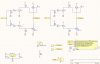
I have made PCB board based on this schematics.
When i put input A on +5V and input B on 0V, motor goes one way, and when A is 0V and B +5V, motor goes the other way. So this is great
The problem is when i try to control the speed with PWM. A is for example on 20% duty cycle, and B is 0% duty cycle, but the motor doesnt run at 20% of its max speed.
Also when inputs are manualy connected to A=+5V and B=0V (motor is running and current is 0.3A), and i disconnect input B (A is still on +5V), it stops and the current is now above 3A (mosfets are designet for 195A and 30A so 3A shouldnt be a problem, but it doesnt work)
Is something wrong with my hardware or with the software (Arduino)?
Code:
int potPin = 3;
int A = 1;
int B = 0;


void setup() {
  pinMode(A, OUTPUT);
  pinMode(B, OUTPUT);
}

void loop() {
  int value = analogRead(A3);


if (value <= 510) {
  value = map(value, 0, 510, 255, 0);
  analogWrite(A, value);
  digitalWrite(B, LOW);
  delay(100);
}

if (value > 510) {
  value = map(value, 510, 1023, 0, 255);
  analogWrite(B, value);
  digitalWrite(A, LOW);
  delay(100);
}
  }
")
