heathtech
New Member
Reworked PCB
OK,
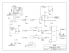
I reworked my Board with the changes proposed. For the sake of simplicity and minimal components, I went with the modified version of my original schematic (i.e. D flip flop in toggle mode) with Len and L. Chungs improvements rather than the more complicated flip flop using set and reset. I added Len's time delay and all of the RC filtering suggested by L. Chung as well as the use of the Schmitt trigger to couple several of the I/O's together. The circuit is working MUCH better without intermittent "skips" on the encoder. There does, however seem to be another problem that might be associated with the capacitor values or the capacitor series resistor values. I might need to speed up the charge/discharge rate by using smaller value resistors. This needs further testing to isolate the exact nature of the problem, so I will conduct tests and another completed schematic when I figure it out.
OK,
I reworked my Board with the changes proposed. For the sake of simplicity and minimal components, I went with the modified version of my original schematic (i.e. D flip flop in toggle mode) with Len and L. Chungs improvements rather than the more complicated flip flop using set and reset. I added Len's time delay and all of the RC filtering suggested by L. Chung as well as the use of the Schmitt trigger to couple several of the I/O's together. The circuit is working MUCH better without intermittent "skips" on the encoder. There does, however seem to be another problem that might be associated with the capacitor values or the capacitor series resistor values. I might need to speed up the charge/discharge rate by using smaller value resistors. This needs further testing to isolate the exact nature of the problem, so I will conduct tests and another completed schematic when I figure it out.