Hello
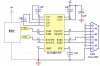
Im trying to interface a GSM modem with PIC18F4220 @ 20MHz ceramic using C18 compiler. The GSM modem is a Siemens Model TC35. For the RS232 im using the 'MAX202CPE' chip
The initial test setup interface with the GSM modem and the PIC seems a failure as im not getting back 'OK' reply from the modem. I know this since the 'OK' is not being displayed on the LCD module hooked to the PIC. The LCD module and the PIC work perfectly as i have tested them seperately to display various strings on the LCD.
Im enclosing in this post my schematic and the test program as below. The test program simply sends out the 'FACTORY DEFAULT' command 'AT&F[0]'. Using this program, the PIC should receive the 'OK' respond reply from the modem. Sadly this does not happen and all seems dead as nothing is being displayed on the LCD.
Please can someone take a look at this and help me please.
Thank you
hhhsssmmm
Code:
#include <p18f4220.h>
#include <delays.h>

#pragma config OSC = HS
#pragma config WDT = OFF
#pragma config LVP = OFF

void SendLCD(unsigned char Byte, unsigned char type); //send byte to print on LCD screen

#define LCD LATD //LCD Latch PORT
#define LCD_RS LATEbits.LATE0 //Register Select (0: Instruction/ 1: Data)
#define LCD_E LATEbits.LATE2 //Enable (Starts data read/write)

unsigned char

				//GSM byte receiving variables
				GSM_Byte_1 = 0,
				GSM_Byte_2 = 0;

void main(void)
{

   ADCON1 = 0x0F; //SET ALL PORTS as DIGITAL I/O

   PORTC = 0; //intialize PORTC
   TRISCbits.TRISC6 = 0; //Serial TX
   TRISCbits.TRISC7 = 1; //Serial RX

   PORTD = 0; //initiallize PORTD
   TRISD = 0x00; //LCD output

   PORTE = 0; //initiallize PORTE
   TRISEbits.TRISE0 = 0;  //LCD Register Select (to LCD Pin 4)
   TRISEbits.TRISE2 = 0;  //LCD Enable (to LCD Pin 6)

   //Configuring below the USART

   TXSTAbits.TX9  = 0; //8bit transmission
   TXSTAbits.TXEN = 1; //transmit enabled
   TXSTAbits.SYNC = 0; //async mode
   TXSTAbits.BRGH = 1; //high speed
   TXSTAbits.TRMT = 1; //TSR empty

   SPBRG = 129; // 9.6kbs baud rate at 20Mhz

   RCSTAbits.SPEN = 1;  //enable serial port
   PIE1bits.RCIE = 1; //enable interrupt upon reception
   RCSTAbits.RX9 = 0;   //8bit reception
   RCSTAbits.CREN = 1;  //enable continous receive
   RCSTAbits.ADDEN = 0; //dissable address detection (9bit)

	INTCON = 0; //Disable all interrupts

	Delay10KTCYx(50); //100ms wait for LCD power up

	//Initialize the LCD
	LCD = 0x00; //clear LCD PORTD pins
	Delay1KTCYx(25); //delay 5mS
	SendLCD(0x03,0); //Initialization command
	Delay1KTCYx(25); //delay 5mS
	SendLCD(0x03,0); //Initialization command
	Delay100TCYx(8); //delay 160uS
	SendLCD(0x03,0); //Initialization command
	Delay100TCYx(8); //delay 160uS
	SendLCD(0x3C,0); //Interface lenght is 8 bits long, 2-lines, 5x10 dots
	Delay100TCYx(8); //delay 160uS
	SendLCD(0x10,0); //Turn off LCD
	Delay100TCYx(8); //delay 160uS
	SendLCD(0x01,0); //Clear LCD
	Delay1KTCYx(25); //delay 5mS
	SendLCD(0x06,0); //Increment the cursor after each byte written
	Delay100TCYx(8); //delay 160uS
	SendLCD(0x0C,0); //Turn on LCD, cursor off, cursor blinking off
	Delay100TCYx(8); //delay 160uS


	//Start up Delay
    Delay10KTCYx(250); //500ms delay


	//Sending out 'Set FACTORY DEFAULT' Command to GSM Modem
	TXREG = 'A';
	while(TXSTAbits.TRMT==0); //wait until transmition is complete
	TXREG = 'T';
	while(TXSTAbits.TRMT==0); //wait until transmition is complete
	TXREG = '&';
	while(TXSTAbits.TRMT==0); //wait until transmition is complete
	TXREG = 'F';
	while(TXSTAbits.TRMT==0); //wait until transmition is complete
	TXREG = '[';
	while(TXSTAbits.TRMT==0); //wait until transmition is complete
	TXREG = '0';
	while(TXSTAbits.TRMT==0); //wait until transmition is complete
	TXREG = ']';
	while(TXSTAbits.TRMT==0); //wait until transmition is complete


	while(PIR1bits.RCIF == 0); //wait for data reply from GSM Modem

	GSM_Byte_1 = RCREG; //reading RCREG clears RCIF

	while(PIR1bits.RCIF == 0); //wait for data reply from GSM Modem

	GSM_Byte_2 = RCREG; //reading RCREG clears RCIF


	//Converting GSM data bytes to ASCII for LCD display
	GSM_Byte_1 += '0';
	GSM_Byte_2 += '0';

	SendLCD(0x80,0); //activate LCD line 1

	//Display GSM acknowledgement 'OK' on LCD
	SendLCD(GSM_Byte_1,1);
	SendLCD(GSM_Byte_2,1);


	while(1); //loop forever


}//end of main()

void SendLCD(unsigned char Byte, unsigned char type)
{

	LCD_RS = type; //Set whether it is a Command (0) or Data/Char (1)

	Delay100TCYx(8); //delay 160uS

	LCD = Byte; //assign the new data to the LCD PORTD

	Delay100TCYx(8); //delay 160uS

	LCD_E = 1; //Set Enable High

	Delay100TCYx(8); //delay 160uS

	LCD_E = 0; //Set Enable Low

}//end of SendLCD()