Continue to Site

Welcome to our site!

Electro Tech is an online community (with over 170,000 members) who enjoy talking about and building electronic circuits, projects and gadgets. To participate you need to register. Registration is free. Click here to register now.

  • Welcome to our site! Electro Tech is an online community (with over 170,000 members) who enjoy talking about and building electronic circuits, projects and gadgets. To participate you need to register. Registration is free. Click here to register now.

Ground References

Status
Not open for further replies.

drkidd22

Member
Hello,

I have a project I'm working on and I have a question about referencing isolated grounds.
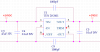
So basically there's GND_A for 24V input and GND_B for a 5V output on a DC-DC converter. The micro-controller is powered by the 5V side which uses GND_B. I need to monitor the voltage of the 24V input at micro end byusing one of its analog input. The only way the analog works is obviously if I connect (jump) GND_A and GND_B. Is this the correct way of doing this or should I be adding some type of circuitry? Any help will be appreciated.
 
Can you show your schematic? If you dont mind the 5V output not being isolated from the 24V then connecting the grounds together is the correct way to do this.
 
Attached is the schematic of the DC-DC converter. My question is more about if I need to add any filtering when connecting the grounds.
 

Attachments

  • DC-DC.PNG
    DC-DC.PNG
    19.2 KB · Views: 176
I meant the whole circuit, this doesnt say much about why you use such costly isolated converter when you could use a buck converter for about a tenth of the price. Do you need that isolation? That will also tell you if you can or cannot connect the two grounds together.
 
If you need to maintain the isolation between your 24V and your 5V supplies, you will need to provide some additional circuitry to monitor your 24V rail with your micro. Perhaps using a good quality opto-isolator or something. If you don't need that isolation, there really is no point in having an isolated supply in the first place, all it does is complicate your circuitry and possibly introduces other issues to your design. The application notes for the device you are using would suggest that a common mode choke should be used close to the device to filter incoming supply variations, also the converter is not internally fused, so make sure you have a fuse somewhere on the 24V side of things :)
 
If you can connect the two grounds together but are concerned about high frequency noise between grounds then you can connect them together through a passive high-pass filter. A large ferrite bead is often sufficient for this purpose.
 
The general rules say keep the returns separate and the together at ONE POINT.

At one time we had analog ground (nice and clean), digital ground (nice and dirty), protective ground. You could have more.

They can be joined with circuitry/filters.

In some buildings there are two separate ground systems. One is protective, the other is a reference.
 
Status
Not open for further replies.

New Articles From Microcontroller Tips

Back
Top